34
06 Electrical Connection User Manual V1.1-2022-12-20
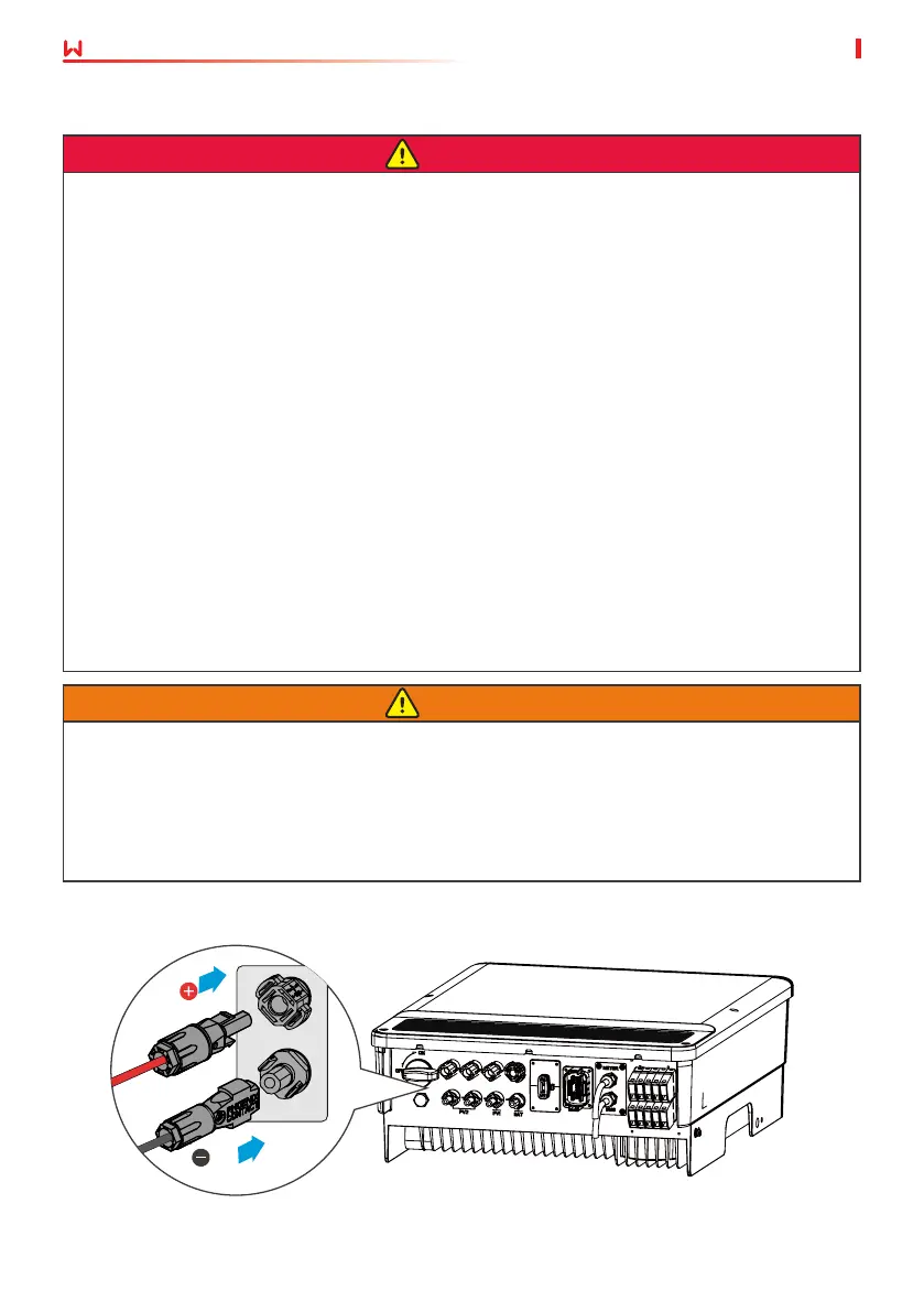
6.5 Connecting the Battery Cable
WARNING
• Connect the battery cables to the corresponding terminals such BAT+, BAT- and grounding
ports correctly. Otherwise it will damage the inverter.
• Ensure the DC cables are connected tightly, securely and correctly.
• Measure the DC cables using a multimeter to avoid reverse polarity connection. Also, the
voltage should be under the permissible range.
DANGER
• The battery used with the inverter shall be approved by the inverter manufacturer. The
approved battery list can be obtained through the ocial website.
• A short circuit in the battery may cause personal injury. The instantaneous high current
caused by a short circuit can release a large amount of energy and may cause a re.
• Before connecting the battery cable, ensure the inverter and the battery, and downstream
& upstream switches, are all disconnected.
• It is forbidden to connect and disconnect the battery cables when the inverter is running.
Otherwise it may cause electric shock.
• Do not connect one battery group to more than one inverter at the same time. Otherwise,
it may damage the inverter.
• It is forbidden to connect loads between the inverter and batteries.
• When connecting battery cables, use insulated tools to prevent accidental electric shock or
short circuit to the batteries.
• Ensure that the open circuit voltage of the battery is within the permissible range of the
inverter.
• Install a DC breaker between the inverter and the battery.
BAT
 Loading...