33
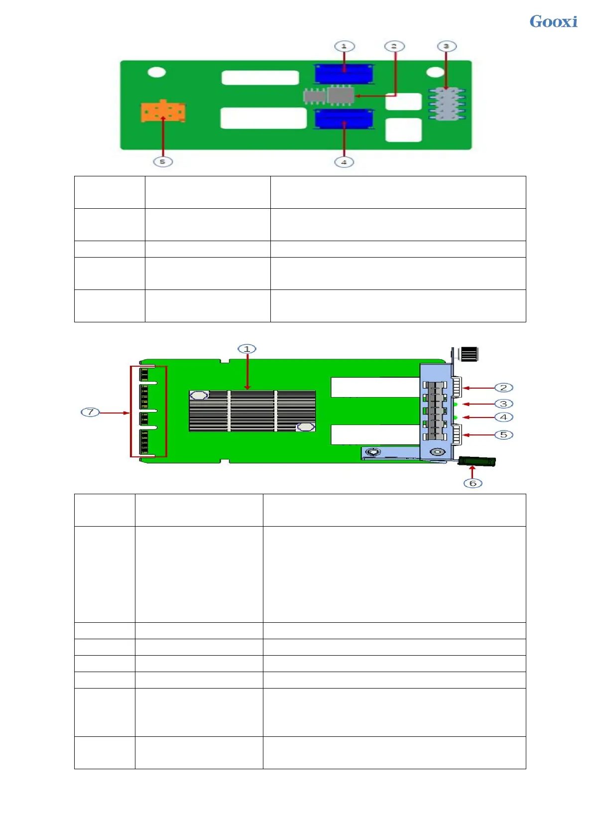
Provides PCIe×4 interface to connect to CPU and NVME
SSD1 (including CPU PEHP I2C and BMC I2C signals)
For data logic processing
JTAG debug interface for programming and version
upgrade of CPLD
4 Pin power socket for docking with PSU or docking with
MB 4 Pin plug to power the board
OCP3.0 network card as shown in the figure
Mainly connected to the network port controller of the
motherboard CPU via PCIe Gen2 X8, which is converted
into a 2-port optical port SFP+ at the network card end, and
the 82599ES chip also provides a port for communication
with motherboard BMC NCSI for info transfer between
BMC & NIC.
Provide SFP+ 10G optical port signal
Provide SFP+ 10G optical port signal
It is used to lock the network card. When removing the
network card, you need to press down to pull out the
network card.
Used to connect to the motherboard OCP3.0 PCIe X8
signal/12V power supply/Sideband signal
 Loading...