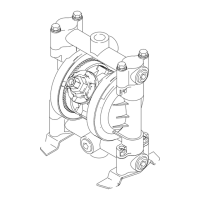
Typical Installation
12 3A9286B
Typical Installation for Models in Explosive Atmospheres or
Hazardous (Classified) Locations
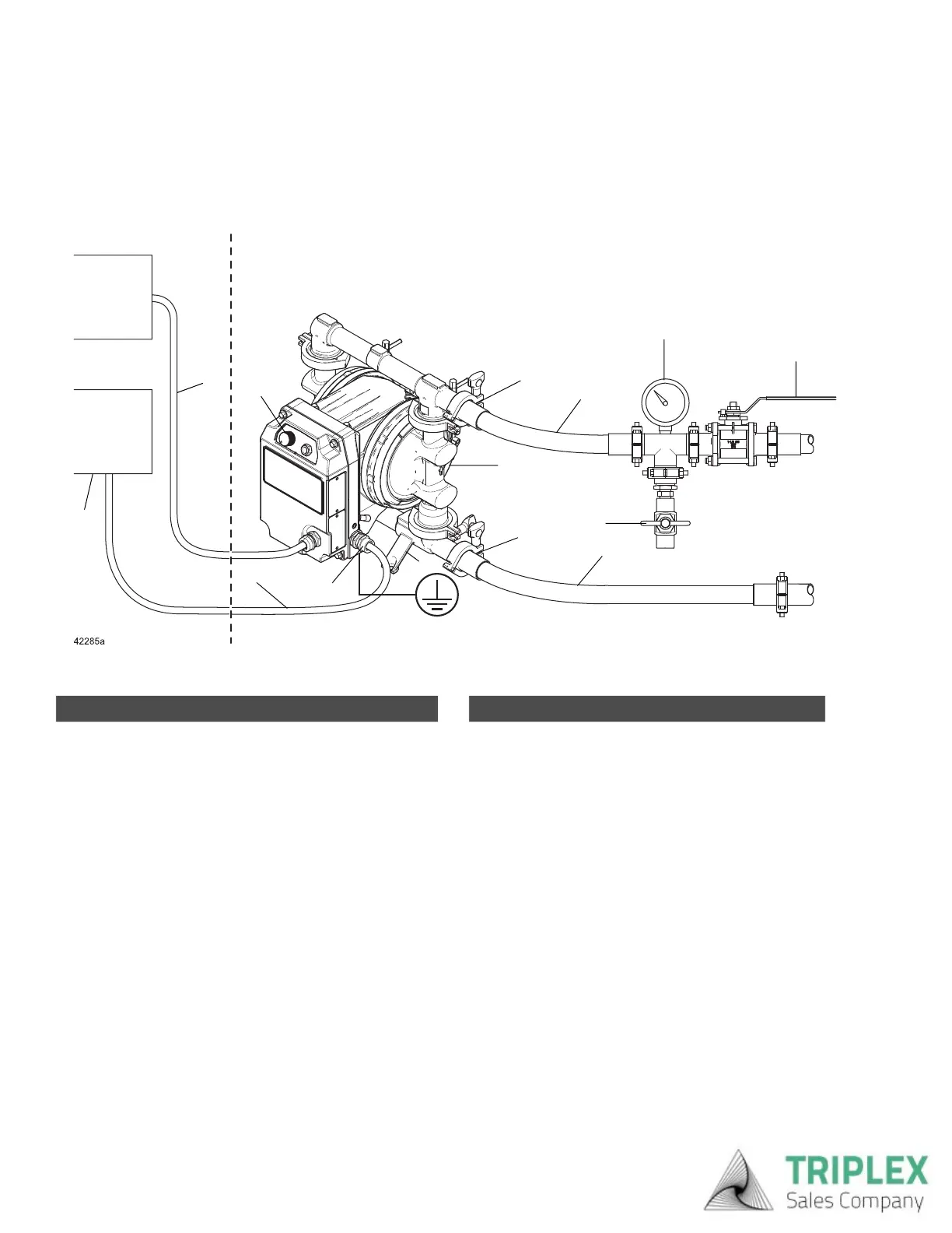
FIG. 4: Typical Installation for Models in Explosive Atmospheres or Hazardous (Classified) Locations (hard wired for
permanent connection) (h30 (QHC) model shown)
\
A
B
C
D
E
F
G
H
J
M
N
K
Explosive Atmosphere or Hazardous (Classified) Location
Ordinary Location
AA
L
Pump Components
A
♦
Power cable
B Fluid inlet port
C Fluid outlet port
D Mounting feet
E Ground fastener
K Fluid output control knob
L
▼
Diaphragm access ports (not shown)
♦
Connect to a circuit with a main electrical disconnect. Install
a branch circuit protective device in each ungrounded
phase. Follow local codes and regulations.
▼
See Install Monitoring Accessories, page 14, or Install
Fluid Leak Line Accessories, page 14.
Accessories (Not Supplied)
F* Conductive, flexible fluid supply line
G* Fluid drain valve
H Fluid shutoff valve
J* Conductive, flexible fluid outlet line
M Fluid pressure gauge
N*
‡
I/O Cable
AA Electrical disconnect
* Required, not supplied.
‡
I/O cable kits are available (purchase separately). See
Related Manuals, page 2.
Triplex Sales
1-847-839-8442
www.triplexsales.com