Service
56 312780K
G250 and G250HR Flow Meters
Removal
1. Follow Preparation, page 52.
2. Unscrew cable from meter connector (CC). F
IG. 32.
3. Unscrew M6 screws (442) and washers (440) from
bottom of meter mounting plate (438) with socket
wrench. F
IG. 32.
4. Disconnect the fluid line from the meter inlet (P).
5. Disconnect the meter outlet (H) fitting from the dose
valve.
6. Service meter as instructed in the meter manual
308778.
Installation
1. Screw meter outlet fitting (H) securely onto the dose
valve inlet, using a wrench.
NOTE: To avoid leakage, secure the meter outlet fitting
(H) to the dose valve before connecting the meter to the
plate (438).
2. Secure meter (M) to plate (438) with screws and
washers (442, 440).
NOTE: You must assemble the meter sensor to the
meter body before connecting the cable to the sensor
for the meter to function properly.
3. Connect cable to cable connector (CC). F
IG. 32.
4. Connect fluid line to meter inlet fitting (P).
5. Calibrate meter as instructed in ProMix Operation
manual.
6. Place board into its correct position and reassemble
RoboMix Panel.
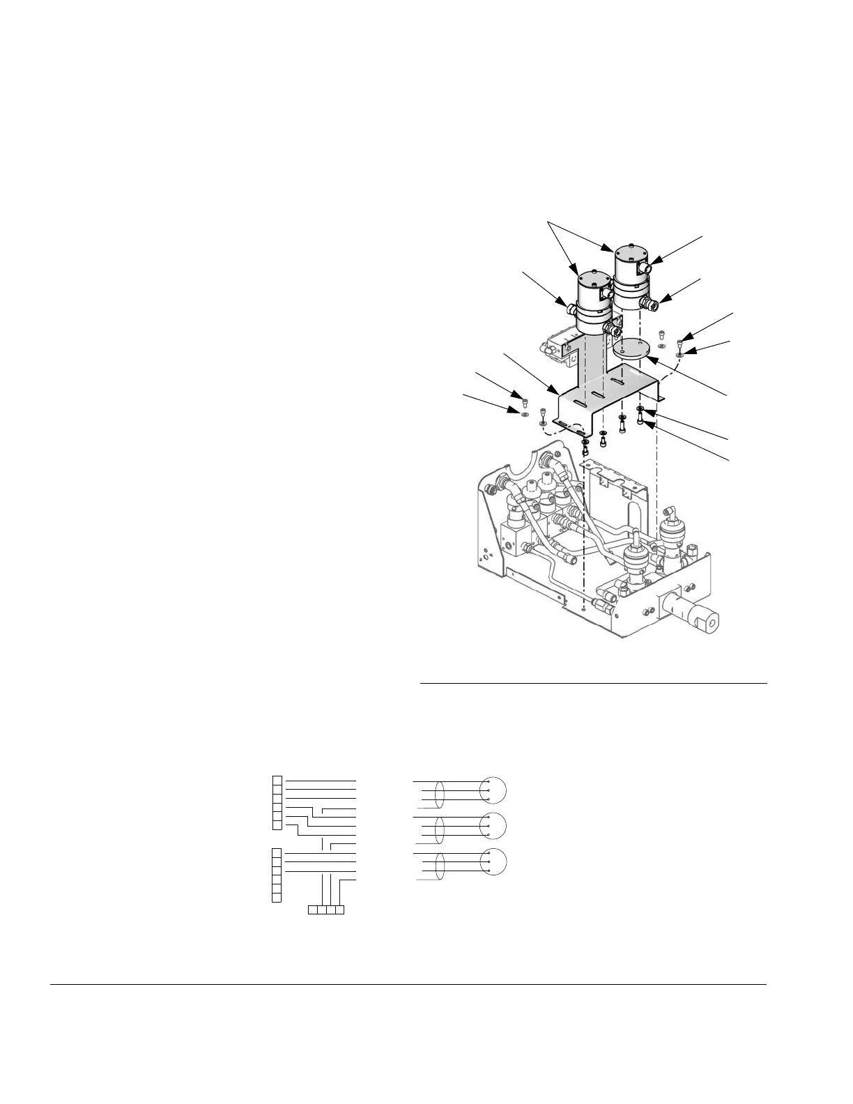
F
IG. 32: G250/G250HR Flow Meters
TI12646a
442
439
440
412
419
M
419
412
438
CC
P
H
FIG. 33: Meter Cable Schematic
1
2
3
4
5
6
J3
PWR (RED)
COM (BLACK)
SIG (WHITE)
SHIELD/GRN
PWR (RED)
COM (BLACK)
SIG (WHITE)
SHIELD/GRN
PWR (RED)
COM (BLACK)
SIG (WHITE)
SHIELD/GRN
FLOW METER A
FLOW METER B
3X CABLE
FLOW METER SOLVENT
1
2
3
4
5
6
J12
GROUND
TERMINAL
*Connectors on Fluid Station Control Board
*
*
 Loading...