Service
60 312780K
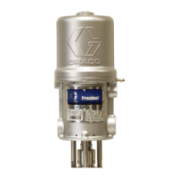
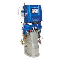
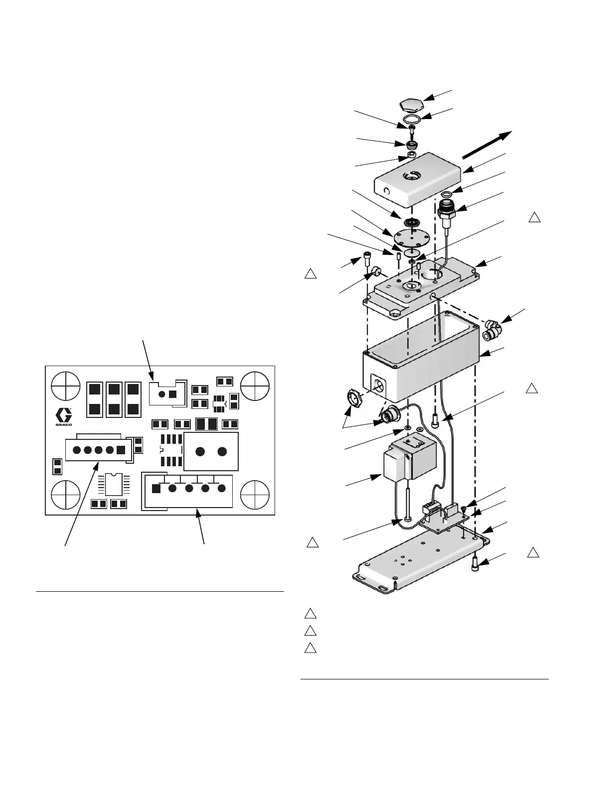
Servicing the V/P Valve
1. Follow Before Servicing, page 40.
2. Remove the four screws (605) holding the bracket
(614) to the housing (611). F
IG. 37.
3. Carefully separate the bracket from the housing and
disconnect the V/P valve cable from J2 on the circuit
board (618). F
IG. 36.
4. Remove the two screws (619a) and o-rings (619b).
Install the new valve (619) with new screws and
o-rings.
5. Reconnect the V/P valve cable to J2 on the circuit
board (618). F
IG. 36.
6. Reattach the bracket (614) to the housing (611).
Torque the screws (605) to 30-40 in-lb (3.4-4.5
N•m).
F
IG. 36: 249179 Flow Control Board
R20
J1
D7 D8 D9
J2
R21
C11
U5
R22
L1
C10
C12
R4
R3
U1
R27
R25
U3
R7
J4
J2 (V/P Valve)
J1 (Power Input)J4 (Pressure Sensor)
FIG. 37: Flow Control
604*
606
620*‡
607
603
605
619
618
621
605
614
601*
624
622
605
*623
*613
*610
*609
*612
*617
*616
611
615
TI12506a
602*‡
619a
619b
Flow
direction
1
2
2
3
2
Torque to 8-10 in-lb (0.9-1.1 N•m)
Torque to 30-40 in-lb (3.4-4.5 N•m)
Torque to 5-7 in-lb (0.6 -0.8 N•m)

 Loading...