7 – 4
7.4 Setting the STEP PASS
Use this function when the distance between the coordinate points defined in the cutting data is extremely
short. The specified STEP PASS value will be used as the minimum unit of distance for processing the
cutting data, permitting stability during initial blade control and improved cutting quality.
Setting Procedure
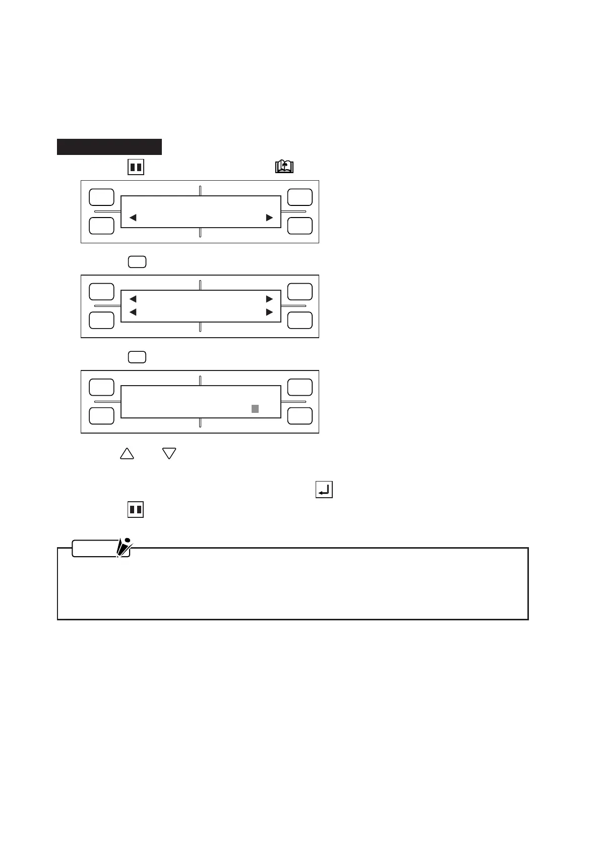
(1) Press the PAUSE key, then press the NEXT PAGE key until the menu below appears.
(2) Press the
F2
(OPTION 1) key to display the menu below.
(3) Press the
F4
(STEP PASS) key to display the menu below.
(4) Use the and POSITION keys to change the STEP PASS setting, which can be specified as
any whole number from 0 to 20.
(5) When the displayed setting is satisfactory, press the ENTER key to register your setting.
(6) Press the PAUSE key to return the plotter to READY status.
NOTE
• Your STEP PASS setting will be retained in the plotter’s RAM even while the plotter is turned off.
• If the STEP PASS setting is too high, your resulting image may not have the intended shape.
Under normal conditions, it is recommended to perform cutting with the STEP PASS parameter
set to zero.
FORCE
SPEED
OFFSET
QUALITY
F1 F3
F4
F2
OPTION1 OPTION2
FORCE
SPEED
OFFSET
QUALITY
F1 F3
F4
F2
UP SPEED OFST ANG
OFST FCE STP PASS
FORCE
SPEED
OFFSET
QUALITY
F1 F3
F4
F2
STEP PASS
STEP PASS = 0