Protected Paths
Planning and Installation Manual 67
DV-33128
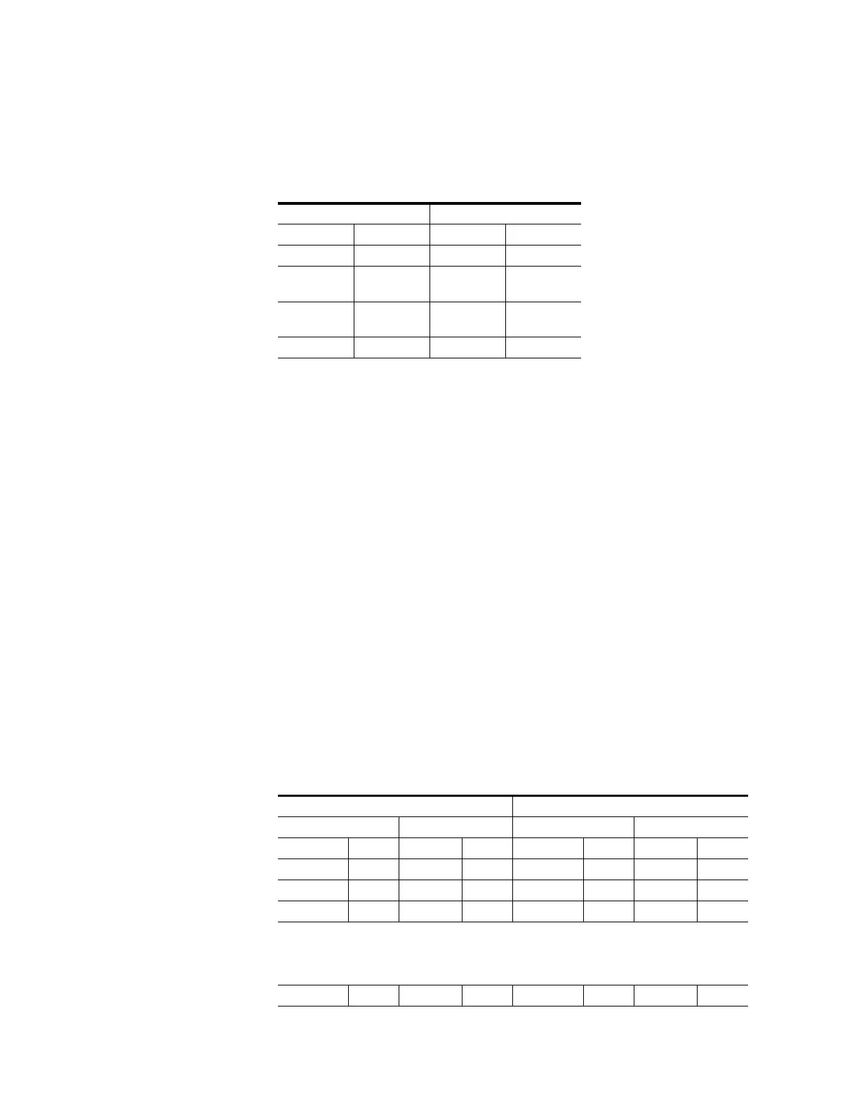
Recommended protected path ranges for DV-33128 routers are as fol-
lows:
For example, to protect an output in the range 1-32, choose a corre-
sponding input in the range 1-32; this will be the primary path. For the
secondary (failover) path, choose an output in the range 33-128 and a
corresponding input in the range 33-128.
This will provide the most independent possible paths through a DV-
33128, i.e., the primary path will use one pair of input and output
boards while the secondary path will use a different pair of boards.
CAUTION With a DV-33128, it isn’t possible to arrange completely independent
paths, i.e., paths that use different matrix boards and power supplies.
Protected path configuration for DV-33128 routers provides redundancy
for input and output boards only.
Note that for a DV-33128 router the maximum number of protected
paths is 64.
A more detailed example is shown in Table 10. This table shows a
sequential wiring scheme for a system yet to be installed or a system
where cables will be re-arranged in a symmetrical pattern in order to
simplify protected path operation.
Ta b l e 9.
Primary path Secondary path
Out In Out In
1-32 1-32 33-128 33-128
33-64 33-64
1-32,
65-128
1-32,
65-128
65-96 65-96
1-64,
97-128
1-64,
97-128
97-128 97-128 1-96 1-96
Table 10. DV-33128 protected paths (example of sequential numbering)
Primary path Secondary path
Out In Out In
Name No. Name No. Name No. Name No.
AirPP 1 MCPP 1 AirSP 33 MCSP 33
Sat1PP 2 StuAPP 2 Sat1SP 34 StuASP 34
Sat2PP 3 StuBPP 3 Sat2SP 35 StuBSP 35
.. ..
.. ..
.. ..
NetPP 64 MainPP 64 NetSP 128 MainSP 128
 Loading...