G16 Smoke Density Monitor
Ver.2.4 – Revision March 2022 17
5.2.1 Welding Sockets – Pre-alignment
The transceiver and reflector with air modules are installed on 200 mm long 1” socket
pipes that are welded onto each side of the stack wall. It is recommended to shorten the
welding sockets to match the thickness of the isolation to increase the stability of the in-
stallation. The welding sockets are of ordinary mild steel. Stability is best achieved by
inserting the welding socket approximately 10 mm into the Ø35 mm hole made in the
stack. This also helps preventing condensate from entering the socket pipe.
Special attention must be given to the alignment of the sockets, so that they are precisely
aligned opposite each other. For pre-alignment, it is recommended to use a guiding pipe
with maximally Ø27 mm outer diameter The guide pipe should be approximately 500 mm
plus stack diameter. This is to be inserted through the 2 x Ø35 mm holes made for the
welding sockets. The welding sockets are then slid onto the guiding pipe and then the sock-
ets are welded to the stack/duct wall see Figure 5-1.
After spot welding the socket pipes, be sure to check for any misalignments. When this is
ensured the welding procedure can be completed in accordance to Figure 5-1.
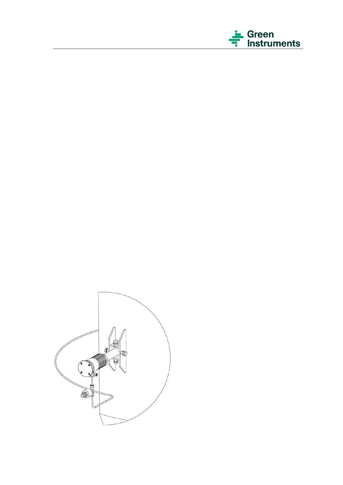
5.2.2 Support and Alignment Brackets (Optional)
In case of walls with thickness less than 6 mm, use the support and alignment brackets
(part no. 02979). After completing the welding of both sockets, the guide pipe or rod can
be removed, and the support and alignment brackets can be mounted and welded in posi-
tion with the socket in center see both Figure 5-1 and Figure 5-2.
Figure 5-2: Mounting of a support and alignment bracket