EasyManua.ls Logo

GREENLINE 40 - Figure 43: Sump Box Position; Figure 44: Sump Box; Figure 45: Sump Box Outlet Valve Position; Figure 46: Sump Box Outlet Valve

GREENLINE 40
137 pages
Print Icon
To Next Page IconTo Next Page
To Previous Page IconTo Previous Page
Loading...
Greenline 40
56
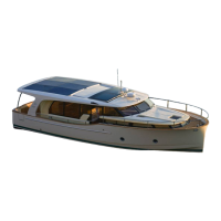
Figure 43: Sump box position
Figure 44: Sump box
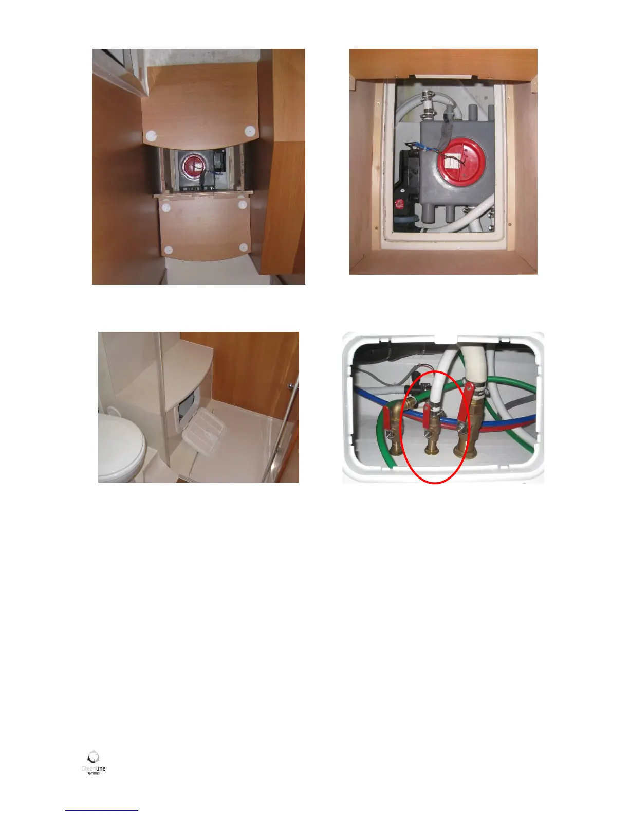
Figure 45: Sump box outlet valve position
Figure 46: Sump box outlet valve
Water from the floor and stuffing boxes flow sat the centre of the boat. A waterproof zone under the engine(s)
receive the possible oil leaks.
The zones are drained by means of an electric pump and the manual pump in the cockpit.

Table of Contents

Related product manuals