GREER Company
1918 East Glenwood Place
Santa Ana CA 92705
Page 29 of 44
MicroGuard
®
586 Operation/Setup Manual
W458200 REV C 10/29/02
Extension Reel Voltage Checks
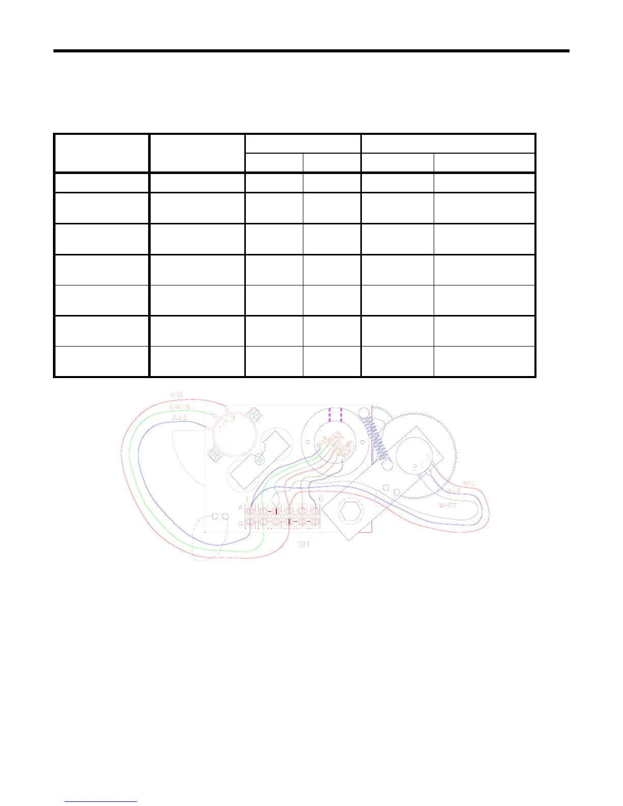
If problems occur with the Two-Block alarm operation, Angle, or Extension sensor, the following chart details
voltage checks that may be made within the extension reel. Follow the action column before measuring voltages
at the specified points in the voltmeter connection columns.
SIGNAL
BOOM POSITION
VOLTAGE VOLTMETER CONNECTION
/ ACTION
MIN MAX RED (+) BLACK (-)
SENSOR DRIVE - +4.7V +5.3V TB1/4 - RED TB1/1 - BLUE
ANGLE SENSOR
OUTPUT
0 Degrees 0.4V 0.6V TB1/2 -
GREEN
TB1/1 - BLUE
EXT’N SENSOR
OUTPUT
0ft (0m) FULLY
RETRACTED
0.15V 0.35V TB1/3 -
WHITE
TB1/1 - BLUE
TWO-BLOCK
DRIVE
A2B WEIGHT
DOWN
5.5V 7.5V TB1/6 -
BLACK
TB1/1 - BLUE
A2B WEIGHT UP 9.5V 10.5V TB1/6 -
BLACK
TB1/1 - BLUE
TWO-BLOCK
SIGNAL
A2B WEIGHT
DOWN
5.5V 7.5V TB1/5 -
BROWN
TB1/1 - BLUE
A2B WEIGHT UP 0V 2V TB1/5 -
BROWN
TB1/1 - BLUE
Notes:
ANGLE SENSOR OUTPUT IS SET TO 10% (1/10
th
) OF SENSOR DRIVE VOLTAGE WITH BOOM AT ZERO
DEGREES.
EXTENSION SENSOR IS SET TO 5% (1/20
th
) OF SENSOR DRIVE VOLTAGE WITH BOOM FULLY
RETRACTED.
MEASURE ALL VOLTAGES WITH A DIGITAL VOLTMETER SET TO DC VOLTS RANGE.
 Loading...