Baserunner V6 User Manual
Rev0
instructions in 7.1 Motor Autotune. Check the checkbox “flip direction on next
autotune”. This will change the default spin direction.
8.3 Wheel Speed Sensing
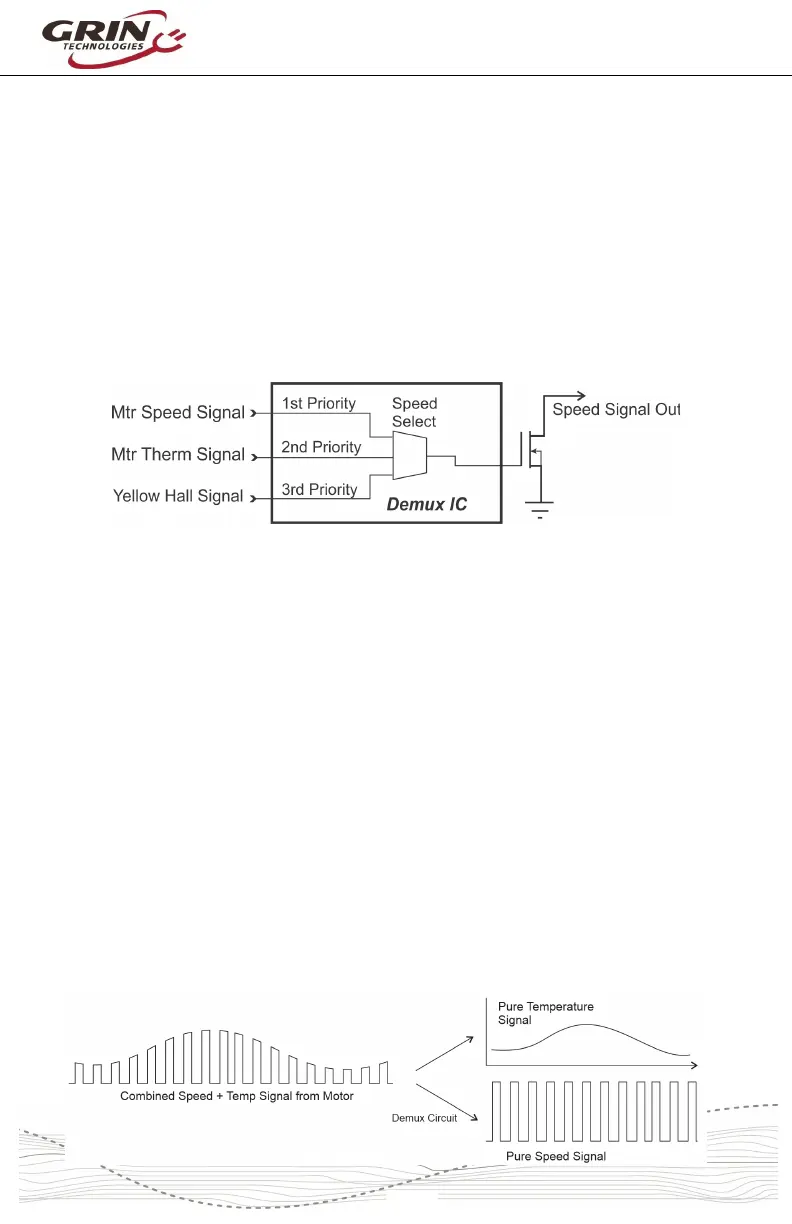
The Baserunner V6 will automatically select the source of the wheel speed signal
for vehicle speed measurement. This is handled in hardware with a separate
demux chip inside the device and can come from one of three sources:
1. The motor speedometer signal (White wire of L1019 cable)
2. The motor temperature signal (Grey in L1019 cable / White in Z910)
3. The motor's yellow hall sensor signal
The chip will look for signals in the priority above, and whichever highest priority
signal is active will get transmitted both to the Cycle Analyst and also the
controller's external speed sensor input (Analog In 3, Brk2).
Notice that the controller and Cycle Analyst (if connected) compute the speed
independently from each other. The Cycle Analyst speed is always based on the
pulse frequency of the “Speed Signal Out” and the configuration in the Cycle
Analyst for pulses/rotation and wheel circumference.
The Baserunner's internal vehicle speed reading depends on the speed signal
source and the controller settings for wheel size and pulses.
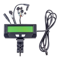
8.4 Combined Temp / Speed Signal
The Baserunner V6 will work with combined temperature and speed signals that
are present on the temperature input pin. If there are no speed pulses present on
the “Wheel Speed” signal, and the temperature signal periodically drops to 0V,
then the Baserunner V6 will treat those 0V pulses as speed signals to track
wheel rotation. These decoded speed and temperature signals are transmitted
both to the CA3 and the controller.