Model T33903/T33904 (Mfd. Since 07/23)
-19-
Anchoring to Floor
Anchoring machinery to the floor prevents tipping
or shifting and reduces vibration that may occur
during operation, resulting in a machine that runs
slightly quieter and feels more solid.
If the machine will be installed in a commercial or
workplace setting, or if it is permanently connect-
ed (hardwired) to the power supply, local codes
may require that it be anchored to the floor.
If not required by any local codes, fastening the
machine to the floor is an optional step. If you
choose not to do this with your machine, we rec-
ommend placing it on machine mounts, as these
provide an easy method for leveling and they have
vibration-absorbing pads.
Lag shield anchors with lag screws (see below)
are a popular way to anchor machinery to a con-
crete floor, because the anchors sit flush with the
floor surface, making it easy to unbolt and move
the machine later, if needed. However, anytime
local codes apply, you MUST follow the anchoring
methodology specified by the code.
Machine Base
Concrete
Lag Screw
Lag Shield Anchor
Flat Washer
Drilled Hole
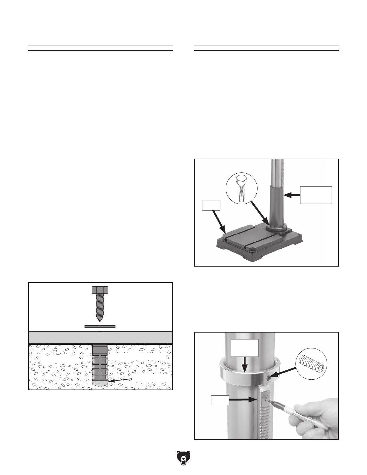
Figure 12. Popular method for anchoring
machinery to a concrete floor.
Anchoring to Concrete Floors
Number of Mounting Holes ............................ 4
Diameter of Mounting Hardware
.................
1
⁄2"
Assembly
To assemble machine:
1.
Attach column assembly to base with M10-
1.5 x 30 hex bolts (see Figure 13).
The machine must be fully assembled before it
can be operated. Before beginning the assembly
process, refer to
Needed for Setup
listed items.
To ensure the assembly process
goes smoothly, first clean any
parts that are
cov-
ered or coated in heavy-duty rust preventative (if
applicable).
Figure 13. Column assembly attached to base.
2.
Mark top of rack, as shown in Figure 14, to
keep track of which end is up.
3.
Loosen set screw shown in Figure 14 to
remove column collar.
Figure 14. Example of marking top of rack.
Rack
Column
Collar
Base
Column
Assembly
 Loading...