-4-
Model T33903/T33904 (Mfd. Since 07/23)
Controls &
Components
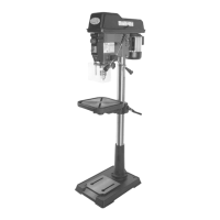
Headstock
Refer to the following figures and descriptions to
become familiar with the basic controls and com-
ponents of this machine. Understanding these
items and how they work will help you understand
the rest of the manual and minimize your risk of
injury when operating this machine.
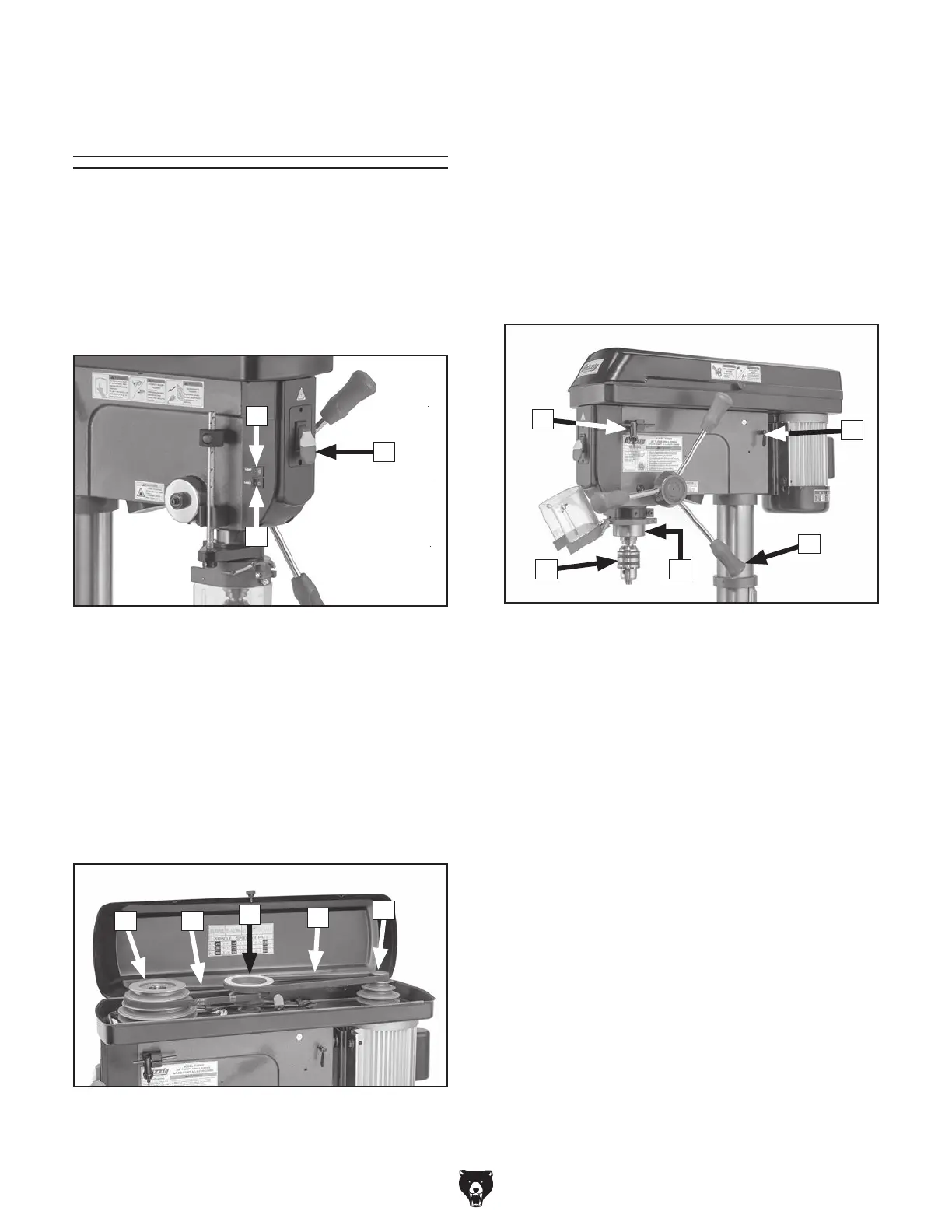
Power Controls
A. LED Switch: Turns LED ON or OFF.
B. ON/OFF Switch w/Disabling Key: Turns
motor ON when moved up; turns motor OFF
when moved down. Removal of yellow key
disables switch so motor cannot start.
C. Laser Switch: Turns laser guide ON or OFF.
Figure 1. Power controls.
A
B
C
D. Spindle Pulley: Holds V-belt and transfers
motor power from idler pulley to spindle.
E. V-Belts: Control spindle speed.
F. Idler Pulley: Hold V-belts and transfers motor
power from motor pulley to spindle pulley.
G. Motor Pulley: Holds V-belt and transfers
motor power to idler pulley.
H. Chuck Key: Adjusts jaws on chuck for drill bit
changes.
I. Belt Tension Lock (1 of 2): Locks motor
position.
J. Downfeed Handle (1 of 3): Moves spindle
down when pulled down. Spindle automati-
cally returns to top position when released.
K. Quill: Houses spindle and spindle bearings.
L. Chuck: Accepts drill bits with shanks from
1
⁄8"–
5
⁄8".
Spindle Speed
Figure 2. Spindle speed components.
E
G
F
ED
J
L K
H
I
Figure 3. Right headstock components.
 Loading...