Maintenance
Replacement Procedures
8-21
(Revised 1/02)
Relay Board - After serial numbers GC7243MS-gas, and
C7439MS-electric
Removal
WARNING
Be sure oven is disconnected from branch circuit power before
performing any repair work.
1. Turn off oven power and disconnect oven from the branch circuit.
2. Remove right hand side panel.
3. Check that the identification labels on all wires connected to the
relays and to the relay board are legible. If they are not legible,
identify and label them at this time.
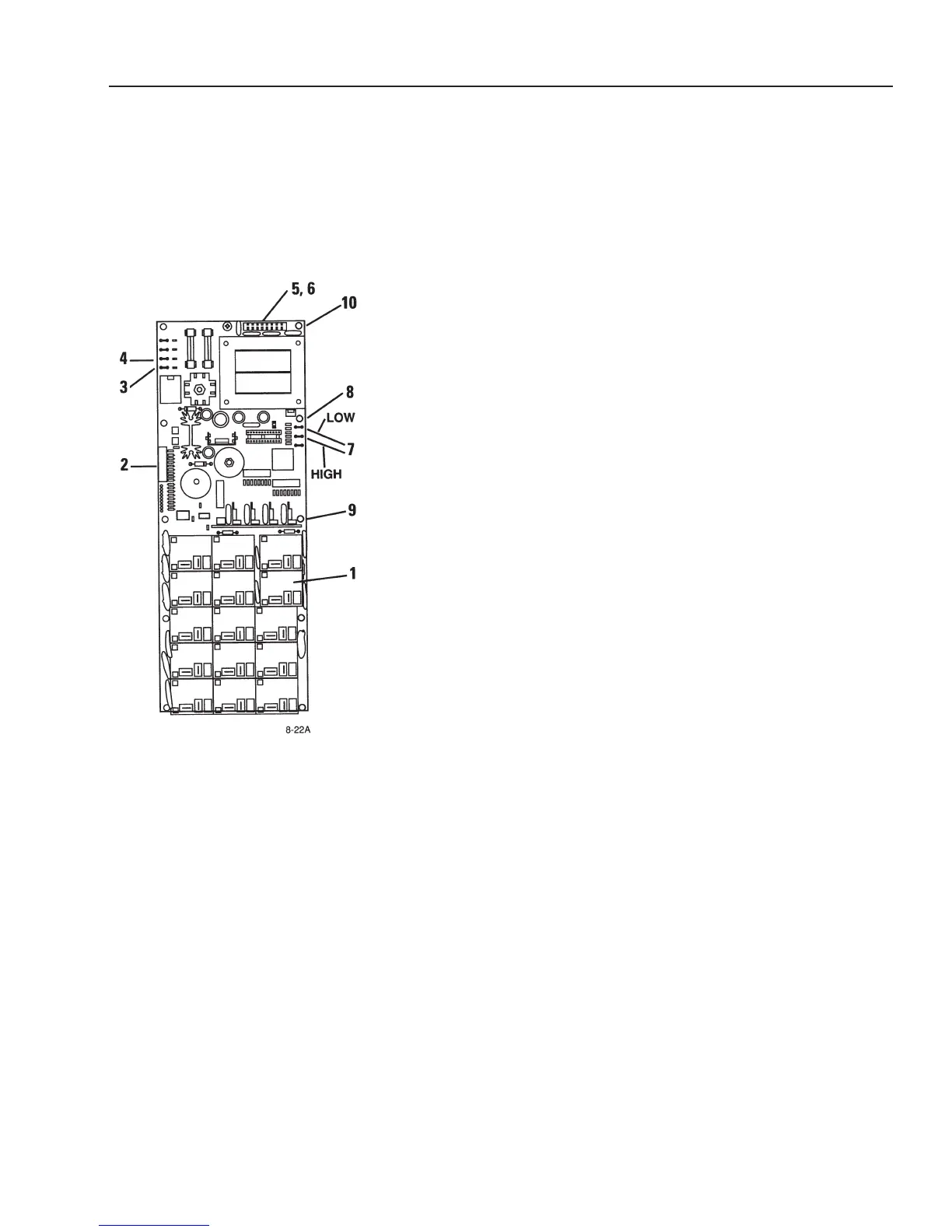
4. Disconnect all electrical leads from relays (1).
5. Disconnect harness (2) from control panel.
6. Disconnect door switch leads from board terminals (3 and 4).
7. Disconnect electrical leads from terminals RB1 (5) and RB2 (6).
8. Disconnect the high and low water level probe leads (7) and ground
wire (8).
9. Remove the seven relay board mounting screws (10). Note that star
washers are used at some of the mounting screw locations. Mark
these locations to ensure correct relay board installation.
Installation
1. Install mounting screws (10) and star washers at locations identified
during removal. Securely tighten all screws except the one that
attaches the water level probe harness ground wire (8).
2. Position ground lead (8) under star washer and mounting
screw (10) and tighten mounting screw
.
3. Correctly connect high and low water level leads (7).
Note “LOW” and “HIGH” wire locations.
4.
Correctly connect leads RB1 (5) and RB2 (6).
5.
Connect door switch leads to terminals (3 and 4).
6. Connect relay board harness (2) to control panel. Make sure the
ribbon connector is attached at both ends.
7. Check for continuity to ground at ground pad (11).
8. Correctly connect relay wires to relays (1).
9. Connect oven to the branch circuit and operate oven. Check that all
touch pad and status lights are illuminated for the selected mode of
operation.
10. Install right side panel.
IMPORTANT
This illustration shows the relay
board for the electric ovens.
However, the relay board used in
the gas ovens is similar.
1.
Relays
2. Relay Board Harness
3. Door Switch Terminal
4. Door Switch Terminal
5.
Terminal for RB1 Lead
6. Terminal for RB2 Lead
7.
High and Low W
ater Level
Probe Leads
8. Water Level Probes Ground
Lead
9.
Hex Head Screw
, 6-32 x 518
inch Long (qty
. 7)
10. Ground Pad