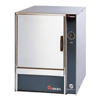
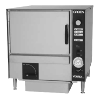
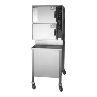
10 SM-GSSP BOILERLESS STEAMER
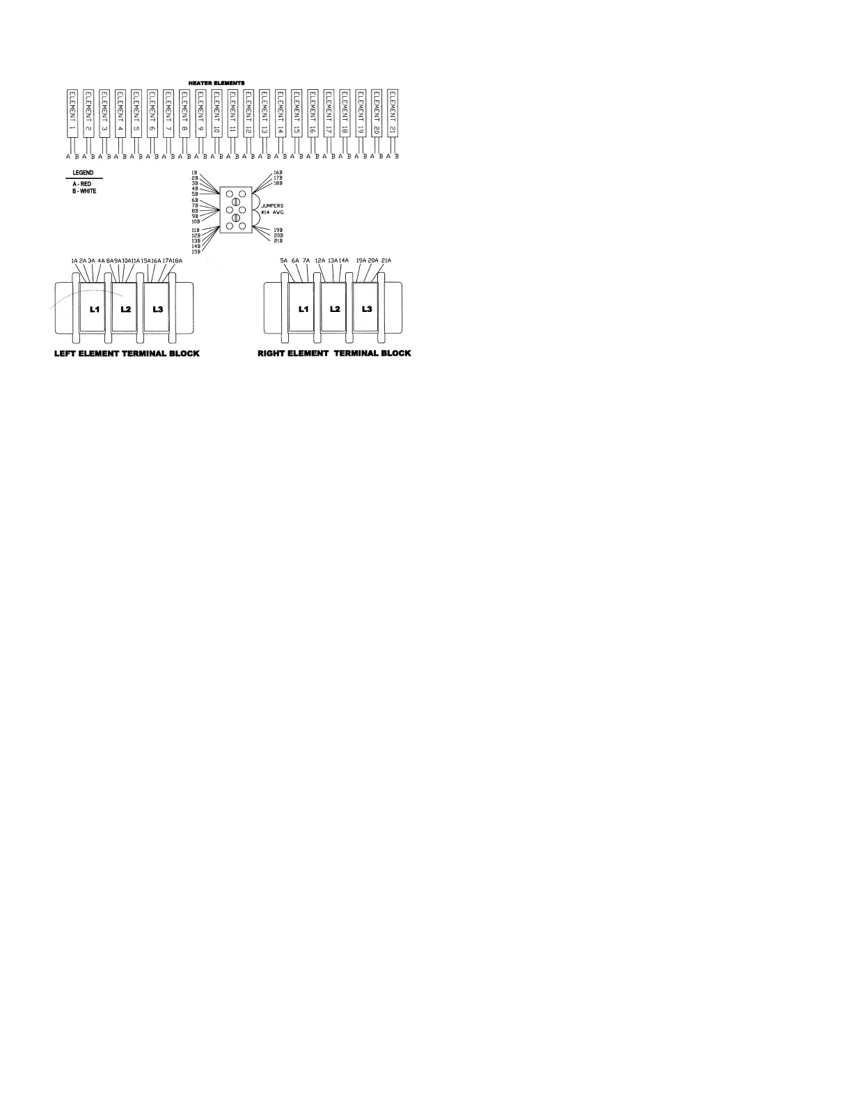
GSSP-BL-10E: 480V 3-PHASE, USING 277V ELEMENTS IN WYE CONFIG.
TROUBLESHOOTING
DIAGNOSTICS
1. Make sure lithium battery is installed in the back of the touchscreen display.
2. Apply power to the GSSP and turn the ON/OFF switch located on the rear
back panel to “on”. The touchscreen should start loading the application
with progress bar. Once loading is complete the touchscreen should go
blank. If the application screen does appear, then check the fuse and both
circuit breakers (one left of the cavity fan motor and one on the control
transformer).
3. Push the power button on the front of the unit. The green LED on the button
should illuminate and “self-diagnostic” should appear. Note: Quickly press
and hold the “menu” button until the unit displays “Entering Service Mode”.
If executed in time, no water should start lling into the reservoir.
4. Press “Service” and enter “9999” then press “Enter”; then press the down
arrow until “Parameters” is shown. Press “Parameters” and enter “7256”
then press “Enter”. Select “Select Model” highlighted in blue and from the
list select the appropriate model being tested and press “Save”.
5. Press the “back” button and select “V***************” highlighted in blue for
entering “Serial Number”. Note: If it is a single cavity unit enter the serial
number using this format: 0000XXXXXXX-X (i.e., 00001234567-1); if it is
double stacked cavity unit, the serial number format 00XXXXXXX-X-T (i.e.,
001234567-1-T). To “T” for top cavity or “B” for bottom, select for the last
character hold to 2 or 8 button for at 1 second.
6. Press the “back” button and select “HH:MM” highlighted in blue for “Time”.
Enter time in HH:MM format and press am/pm for the appropriate and press
“Save”.
7. Press the “back” button and select “MM/DD/YYYY” highlighted in blue for
“Date”. Enter date in MM/DD/YYYY format and press “Save”. Press “Accept”
if date is correct or “Change” if date needs corrections.
8. Press the “back” button and select “MM/DD/YYYY” highlighted in blue for
“Manufacturing Date”. Enter date in MM/DD/YYYY format and press “Save”.
Press “Accept” if date is correct or “Change” if date needs corrections.
9. Press the “back” button to “Service” menu and select “Diagnostics”. Before
continuing visual check and make sure all harnesses are in place and the
connectors are properly seated. “Board Communication” status should be
“Active” in green for proper communication between touchscreen display
and I/O board. Check I/O board for ashing blue LED. No communication or
break in communication for more than 5 seconds will show “Lost” status.
10. Scroll down to “Control Voltage” and conrm the value for 24 VAC at the
secondary of the control transformer. Values should be between 22 and 26
VAC and solid red LED on I/O board. Record value on sheet 8.
11. Check “Board Temp” value and conrm temperature inºF/C. The value
should between 70°F(21°C) and 149°F(65°C). Record value on sheet 8.
12. Check “High Limit Thermostat”, “Ready Tstat”, “Hold Tstat”, and Condensate
Tstat status and conrm their states. All thermostat status should read
“Closed” on the touchscreen display.
13. Disconnect one wire lead from high limit thermostat, status should change
next “High Limit Thermostat” from “Closed” to “Open” on the touch screen
display. Reconnect lead and status should change back to “Closed”.
• Repeat step #13 for the following components:
- Ready Thermostat
- Hold Thermostat
- Condensate Thermostat
14. Scroll up to “Circulation Fan” and turn it on for 10 seconds and off for 5
seconds. Repeat cycle 2 times. When fan is on there should be an orange
LED on the I/O board and orange LED when it is off.
15. Turn on “Fill Valve” for 5-10 seconds and conrm the mA value. Values
should between 240 and 360 mA and solid red LED on I/O board. Then turn
valve off and value should drop to 0 mA with red LED turned off on the I/O
board.
16. Turn on “Drain Valve” for 5-10 seconds and conrm the mA value. Values
should between 480 and 720 mA and solid red LED on I/O board. Then turn
valve off and value should drop to 0 mA with red LED turned off on the I/O
board.
17. Turn on “Condensate Valve” for 5-10 seconds and conrm the mA value.
Values should between 240 and 360 mA and solid yellow LED on I/O board.
Then turn valve off and value should drop to 0 mA with yellow LED turned off
on the I/O board.
18. Turn on “Cooling Fan” for 5-10 seconds and conrm the mA value. Values
should between 50 and 260 mA (no LED on I/O board). Then turn valve off
and value should drop to 0 mA.
19. Check “Water Level Low”, “Water Level High”, and “Water Level Overow”
probe status and conrm their states. All probe status should read “Open” on
the touchscreen display and no LEDs on the I/O board should be illuminated.
20. With one end of a jumper wire attach or touch the metal tip of the low
probe inside the cavity; with the other end of the jumper wire, ground to the
cavity bottom, status should change next “Water Level Low” from “Open” to
“Closed” on the touch screen display and the low probe orange LED should
illuminate on the I/O board. Remove the jumper wire and “Water Level Low”
from “Closed” to “Open” on the touch screen display and the low probe LED
should turn off the I/O board.
• Repeat step #20 for the following water level probes:
- High water level probe (yellow LED)
- Overow water level probe (red LED)
21. Press back button to exit “Diagnostics” menu and afrm “Restart” to
continue to functional test.


 To Next Page