6 SM-GSSP BOILERLESS STEAMER
AMPERAGE/RESISTANCE CHART
Model Voltage/Phase Amperage Resistance
GSSP-BL-3E 208 3-PHASE 25 8.3
GSSP-BL-3E 240 3-PHASE 22 10.9
GSSP-BL-3E 480 3-PHASE 11 43.6
GSSP-BL-3E 208 1-PHASE 44 4.7
GSSP-BL-3E 240 1-PHASE 38 6.3
GSSP-BL-5E 208 3-PHASE 34 6.1
GSSP-BL-5E 240 3-PHASE 29 8.3
GSSP-BL-5E 480 3-PHASE 15 32
GSSP-BL-5E 208 1-PHASE 58 3.6
GSSP-BL-5E 240 1-PHASE 50 4.8
GSSP-BL-10E 208 3-PHASE 59 3.5
GSSP-BL-10E 240 3-PHASE 51 4.7
GSSP-BL-10E 480 3-PHASE 26 18.5
GAS MODEL INSTALLATION
Although Groen recommends the SmartSteam Pro Boilerless Steamer is installed
near non-combustible surfaces, the following minimum clearances are to any
surface, combustible or non-combustible.
Right Side: 2 inches
Left Side: 2 inches
Rear: 6 inches
However, for easy service, at least 6 inch clearance should exist for right side
access to gas shut-off valve.
The unit must be installed in a well-ventilated room with an adequate air supply.
The steamer must be installed beneath a ventilation hood since gas combustion
products exit the appliance.
Any item which might obstruct the ow of air for combustion and ventilation
must be removed. Do not obstruct the ue cover or rear vents after installation.
The area directly around the appliance must be cleared of all combustible
material. The installation must conform with local codes or, in the absence of
local codes, with the National Fuel Gas Code, ANSI Z223.1/NFPA 54, or the
National Gas and Propane Installation Code, CAS B149.1.
The unit and its individual shutoff valve must be disconnected from the gas
supply system during any pressure testing of that system which has test
pressures in excess of ½ PSI (3.45kPa). It must be isolated from the gas supply
piping system by closing its individual manual shutoff valve during any pressure
testing of the gas piping system which has test pressures equal to or less than
½ PSI (3.45 kPa).
ELECTRICAL SUPPLY CONNECTION
Provide 115 VAC, 60 HZ, 1 PH, 15 AMP service. Bring wire in through hole on
the back panel. Each cavity requires a separate cord for connection. Local codes
and/or the National Electrical Code should be observed in accordance with ANSI/
NFPA 70. AN ELECTRICAL GROUND IS REQUIRED. The wiring diagram, located
in the service compartment and in this manual. Maximum load is 2-1/2 AMPS.
In Canada provide electrical service in accordance with the Canadian Electrical
Code, CSA C22.2 part 1 and/or local codes.
GAS SUPPLY CONNECTION
Connection to the gas supply shall be in accordance with the chart below. Supply
pressure must be at least 4.5” W.C. (maximum 14” W.C.) for natural gas or 12”
W.C. (maximum 14” W.C.) for LP gas. In Canada, the installation must conform
to the Canadian Gas Code, CAN 1-B149. Installation Codes for Gas Burning
Appliances and Equipment and/or local codes. Check all gas connections for
leaks prior to unit operation.
RATINGS FOR GAS CHART
Model BTU
OPERATING
PRESSURE
INCOMING GAS FEED RATE
MIN MAX
3G Natural 54,000 4.30” WC 5”WC 14” WC
3G Propane 54,000 10.5” WC 12” WC 14” WC
5G Natural 58,000 4.30” WC 5”WC 14” WC
5G Propane 58,000 10.5” WC 12” WC 14” WC
10G Natural 100,000 4.30” WC 5”WC 14” WC
10G Propane 100,000 10.5” WC 12” WC 14” WC
INSTALLATION
NOTICE: THE QUALITY OF THE WATER IS A FACTOR IN THE PROPER PERFORMANCE
OF THE STEAMER. THE WATER SUPPLY SHOULD HAVE A MINIMUM VALUE
OF 30-40 PARTS PER MILLION OF TOTAL DISSOLVED SOLID (TDS).
Many of the problems associated with the degraded performance or non-
operation of the SmartSteam Pro Boilerless Steamer can be traced directly to
improper installation and/or lack of proper and periodic cleaning-all of which is
the responsibility of the customer.
This section is provided to determine that the equipment was installed correctly,
to indicate the proper cleaning techniques ads to be used by Groen customers
and steamer test procedures.
It is to be expressly noted that ALL work associated with the installation and
cleaning of the SmartSteam Pro Boilerless Steamer is NOT covered by the Groen
warranty provisions.
WATER CONNECTION
Make sure that the incoming water connection is made with a ¾” N.H. COLD
water supply hose. Rigid pipe is not required. The water pressure should be
between 30 and 60 PSIG. Higher pressures will require the use of a pressure
regulator. Make sure that all connections are tight with no leaks-no matter how
small.
LEVEL INSTALLATION
It is preferable that the steamer be installed level side to side (left to right) and
slightly pitched (1 to 5 degrees) back to front, with the front always being lower
that the rear. This allows the condensate water to go to the drain at the front of
each cavity.
Make sure that all leg extensions are tight against the oor and that the steamer
is supported on all four legs.
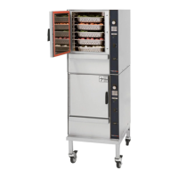
DRAIN LINE INSTALLATION
The drain line should not be less than 1-1/2” – for single units, 2” (5E) – for
double stacked units.
There must be a 2” air gap to the (non-pressurized) building drain. Make sure
that the drain is sloped AWAY and DOWN from the steamer and that there are
no obstructions in the line. Failure to observe these requirements may cause a
water trap in the drain line and produce enough back pressure to prevent proper
cavity draining –resulting in condensate water leaking from the door. Drain line
must NOT be made of plastic pipe. It must be able to withstand boiling water.