15
English (US)
6.7.1 Engine-driven generators
If the submersible pump is going to be operated
by an engine driven generator, we suggest that
you contact the manufacturer of the generator to
ensure the proper generator is selected and
used. See section 10.2 Guide for engine-driven
generators in submersible pump applications for
generator sizing guide.
If power is going to be supplied through
transformers, section 10.3 Transformer capacity
required for three-phase submersible motors
outlines the minimum KVA rating and capacity
required for satisfactory pump operation.
6.7.2 Control box or panel wiring
Single-phase motors
Connect single-phase motors as indicated in the
motor control box.
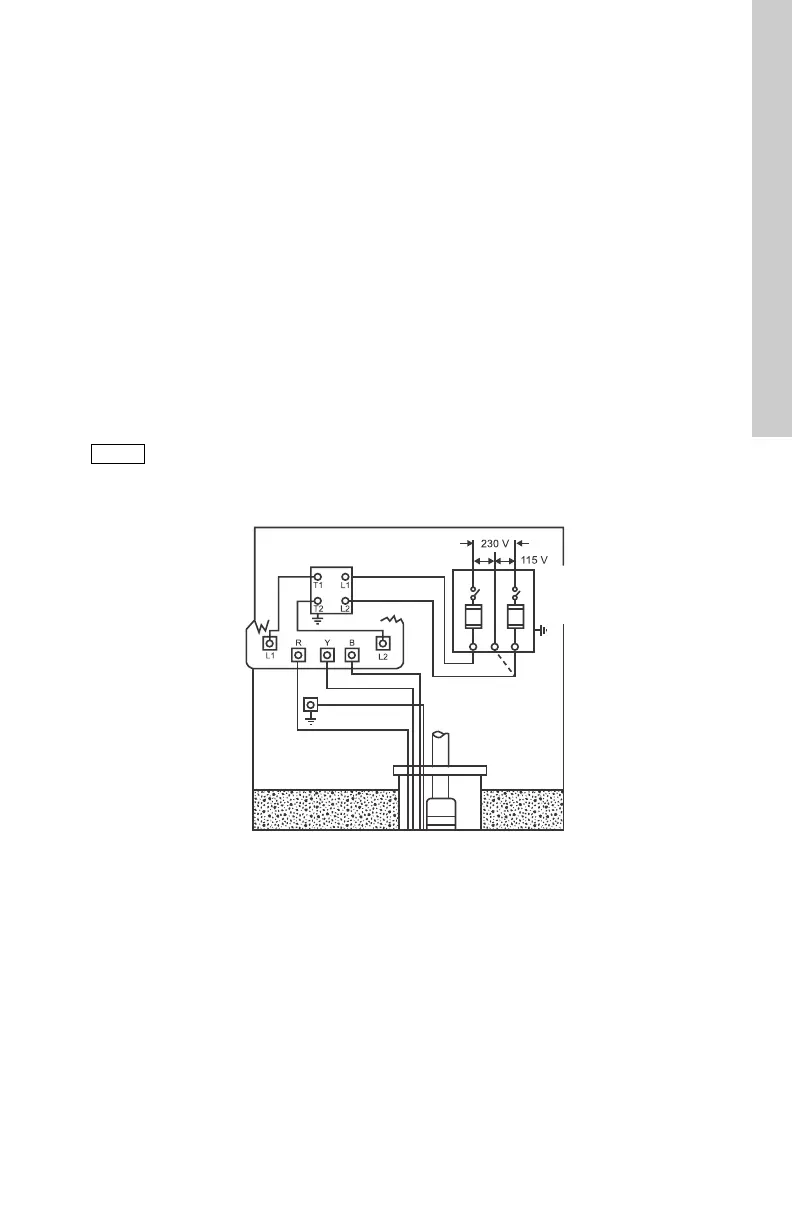
A typical single-phase wiring diagram using a
Grundfos control box is shown in fig. 11.
Fig. 11 Single-phase wiring diagram for Grundfos control boxes
CAUTION
Motor burnout protection via CUE,
CU331SP, or MP 204.
Use approved dry-run protection such
as with MP 204.
TM05 0037 2413
Control box
Fused
disconnect
switch
Red
Green
Yellow
Black
Use dotted line for
115 V operation
Well seal
Pressure
switch