26
English (US)
9.1 Preliminary tests
Test How to measure What it means
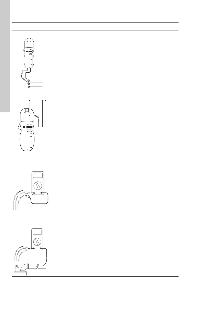
Supply voltage
TM00 1371 5092
By means of a voltmeter set to the
proper scale, measure the voltage
at the control box or starter.
• On single-phase units, measure
between line and neutral.
• On three-phase units, measure
between the legs (phases).
When the motor is under load, the
voltage must be within ± 10 % of the
nameplate voltage. Larger voltage
variation may cause winding
damage.
Large variations in the voltage
indicate a poor power supply and
the pump must not be operated until
these variations have been
corrected. If the voltage constantly
remains high or low, the motor must
be changed to the correct supply
voltage.
Current
TM00 1372 5082
• By means of an ammeter set to
the proper scale, measure the
current on each power lead at the
control box or starter. See section
10.6 Electrical data for motor
amp draw information.
• Current must be measured when
the pump is operating at a
constant outlet pressure with the
motor fully loaded.
If the amp draw exceeds the listed
service factor amps (SFA), or if the
current imbalance is greater than 5
% between each leg on three-phase
units, check for the following:
• Burnt contacts on motor-
protective circuit breaker.
• Loose terminals in starter or
control box or possible cable
defect. Check winding and
insulation resistances.
• Supply voltage too high or low.
• Motor windings are shortened.
• Pump is damaged, causing a
motor overload.
Winding resistance
TM05 0028 0511
• Turn off power and disconnect
the submersible drop cable leads
in the control box or starter.
• By means of an ohmmeter, set
the scale selectors to Rx1 for
values under 10 ohms and Rx10
for values over 10 ohms.
• Zero-adjust the ohmmeter and
measure the resistance between
leads. Record the values.
• Motor resistance values can be
found in section 10.6 Electrical
data. Cable resistance values are
in section 6.7.7 Insulation
resistance and ohm value chart.
If all the ohm values are normal,
and the cable colors correct, the
windings are not damaged.
If any one ohm value is less than
normal, the motors may be shorted.
If any one ohm value is greater than
normal, there is a poor cable
connection or joint. The windings or
cable may also be open.
If some of the ohm values are
greater than normal and some less,
the submersible drop cable leads
are mixed. To verify lead colors, see
resistance values in section
10.6 Electrical data.
Insulation resistance
TM05 0029 0511
• Turn off power and disconnect
the submersible drop cable
leads in the control box or
starter.
• By means of an ohmmeter or
megohmmeter, set the scale
selector to Rx 100K and zero
adjust the meter.
• Measure the resistance between
the lead and ground (discharge
pipe or well casing, if steel).
For ohm values, refer to section
9.2 Checking pump performance.
Motors of all hp, voltage, phase and
cycle duties have the same value of
insulation resistance.