21
English (US)
6.7.6 Wiring checks and installation
Before making the final surface wiring
connection of the submersible drop cable to the
control box or control panel, it is a good practice
to check the insulation resistance to ensure that
the cable and splice are good. Measurements
for a new installation must be at least 200
megaohms. See the table in section
6.7.7 Insulation resistance and ohm value chart.
If the insulation resistance of the cable and
splice is measured at higher than 200
megaohms, run the submersible drop cable
through the well seal by means of a conduit
connector to prevent foreign matter from
entering the well casing.
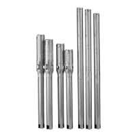
Always protect the submersible drop cable with
conduit from the pump to the control box or
control panel. See fig. 16.
Finish the wiring and verify that all electrical
connections are made in accordance with the
wiring diagram.
Check to ensure that the control box or control
panel and high-voltage surge arrester have been
grounded.
Route conductors properly such as in conduit
where called for by Local Code to protect the
conductors.
6.7.7 Insulation resistance and ohm value
chart
Insulation resistance in a submersible pumping
system is a measure of the ability of the motors
and/or cables to withstand normal voltage and
transient voltage without breakdown and failure.
An "adequate" level of insulation resistance is
not a constant value, but depends on the
installation voltage and conditions, and whether
the measured resistance is lowered by a specific
weak point or by widely distributed conductance
such as in cable insulation material itself. For
this reason, values for acceptable resistance
cannot be specific.
Insulation resistance measurements
Measure insulation resistance at the time of
initial motor installation and periodically
thereafter. In deep set submersible installations,
take measurements throughout the installation
process to detect potential cable insulation or
connection damage before the unit is completely
installed. The insulation resistance table in this
section describes the condition of the insulation
system for a submersible motor system of 600 V
or less, based on megohmmeter readings.
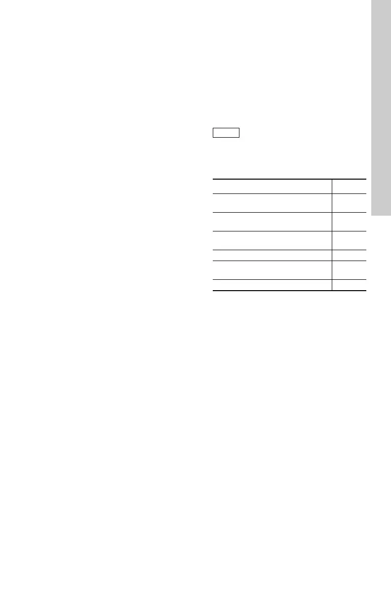
The table below shows suggested values of
insulation resistance and the test voltage in
relation to the rated voltage of the motor.
If the rated motor voltage is less than or equal to
500 V, the insulation resistance must be
measured at a test voltage of 500 VDC.
If the rated motor voltage is greater than 500 V,
the insulation resistance must be measured at a
test voltage of 1000 VDC.
Measure the insulation resistance in
accordance with local codes and
regulations.
Rated voltage ≤ 500 [V] > 500 [V]
Condition of motor and
cable
[MΩ][MΩ]
New motor without
submersible drop cable
≥ 200 ≥ 200
Used motor which can be
re-installed in well
≥ 10 ≥ 10
New motor in well ≥ 20 ≥ 20
Motor in good condition
in well
≥ 0.5 ≥ 1
Damaged insulation < 0.5 < 1
 Loading...