20
English (US)
True grounding points are considered to be one
of the following:
• a grounding rod driven into the water strata
• a steel well casing submerged into the water
lower than the pump installation depth
• steel outlet pipes without insulating
couplings.
If plastic outlet pipe and well casing are used or
if a grounding wire is required by local codes,
connect a properly sized, bare copper wire to a
stud on the motor and run to the control panel.
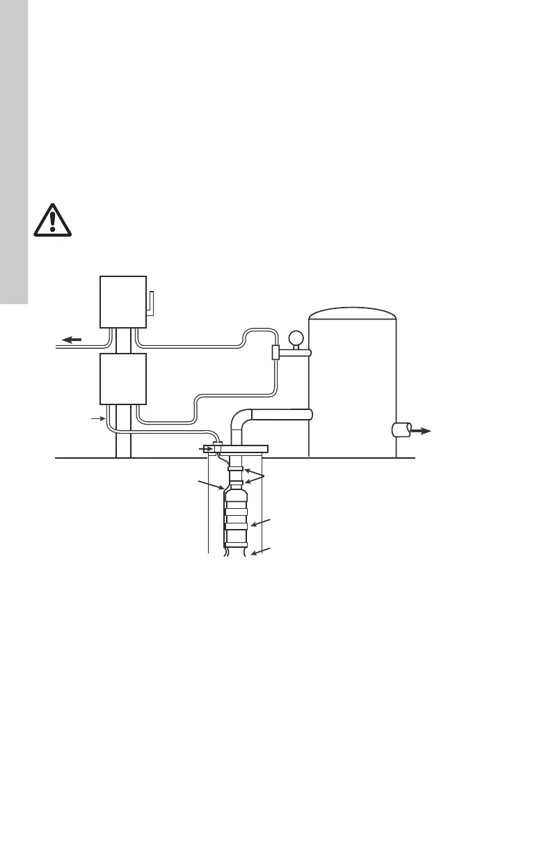
Fig. 16 Wiring and installation diagram
WARNING
Do not ground to a gas supply line.
Connect the grounding wire to the
ground point first and then to the
terminal in the control box or control
panel.
TM05 0041 0611
Power
supply
Electrical
dis-
connect
box
Control
box
House
supply
Conduit
connector
Submersible
drop cable
Pressure
gauge
Pressure
switch
Pressure
tank
Well
seal
Tape
Pump
Motor
Conduit*
* Conduit for proper support and
protection of the cable against
damage between the motor and
the point of supply connection.