AWT35‐500349|June2009 Page3
1.0 Installation
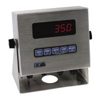
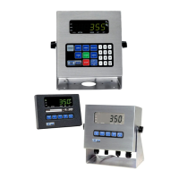
The standard Model 350 zinc die cast enclosure is a NEMA1 (IP 20) equivalent. The Model 350/355
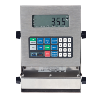
stainless steel enclosure meets NEMA 4X/IP65 type specifications.
WARNING: Risk of electrical shock! Service of the indicator should
only be performed by authorized service personnel.
If the Model 350/355 is being plugged into an outlet, it must have an
earth ground. Make sure the supply voltage from the outlet meets the
requirements of the indicator.
When choosing a mounting location for the Model 350 die cast, ensure
that the unit is not installed in a wash-down area or conductive dust
environment.
1.1 Desktop Mounting
The die cast enclosure is designed for desktop mounting. When set on a flat surface, the front face is angled
for easy viewing. An optional swivel bracket is available for a broader range of viewing. All wiring enters
from the rear and can be secured with the included screw mounted cable ties.
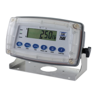
The stainless steel models have a swivel bracket for quick adjustment of viewing angle.
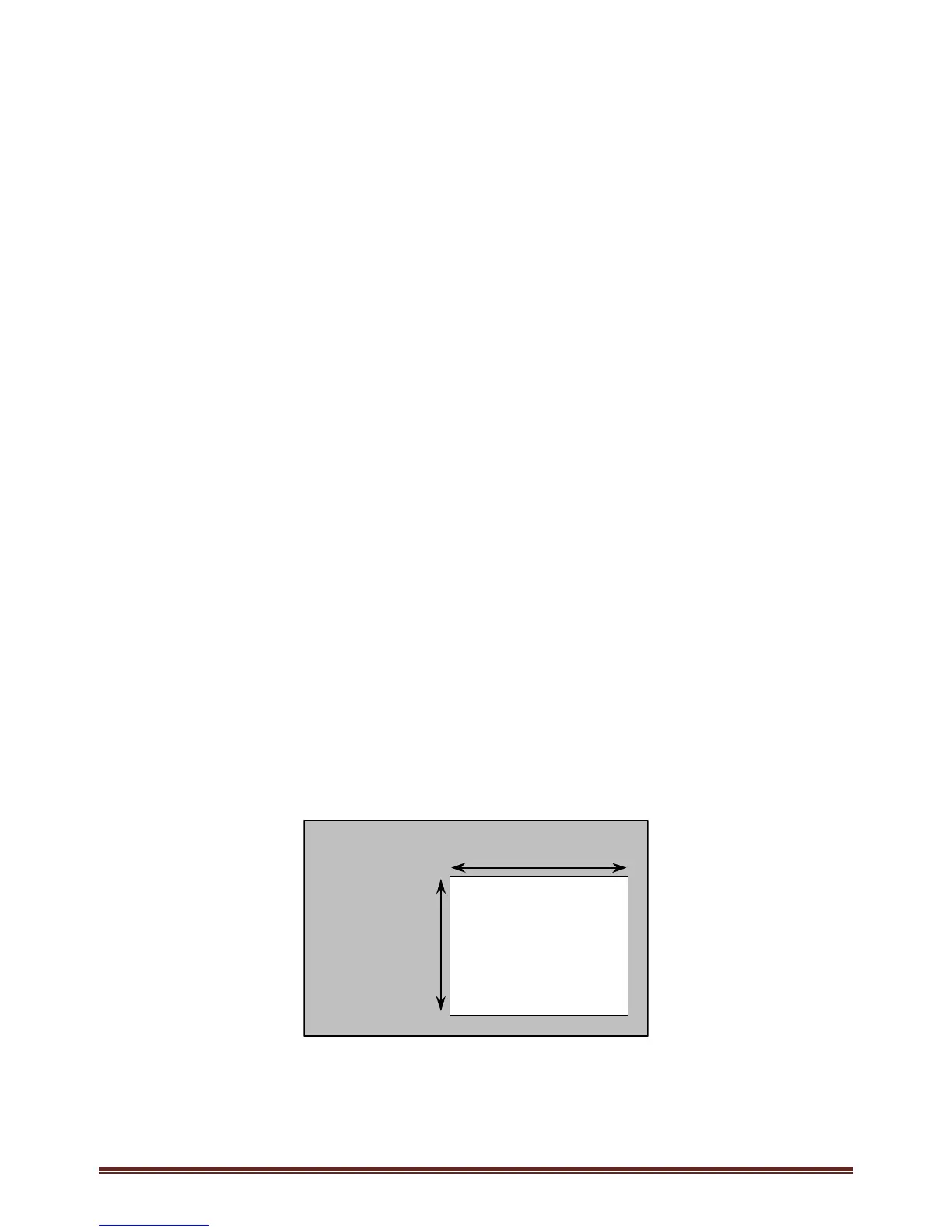
1.2 Panel Mounting (350 Die Cast Only)
The optional panel mount kit allows the zinc die cast enclosure to be installed in a user panel. Allow for 2.00"
(57.2mm) depth behind the panel surface. See the Panel Mount cutout drawing below for dimensions.
7.33” – 7.45”
186.2 – 189.2mm
5.25” – 5.37”
133.4 – 136.4mm
PANEL
CUTOUT