35
APCD-500, rev10
APCD-500
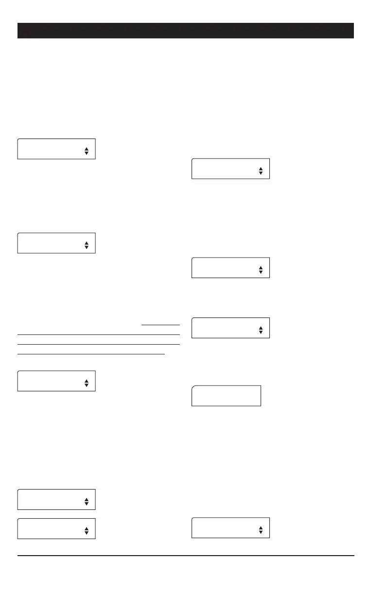
Window Size — This parameter is used to
restart a drive unit that was stopped due to an
over current condition. The drive unit restarts
when its amperage draw becomes lower than
its respective “Max Current Consumption - Win-
dow Size”. The window size is common to all
drive units and ranges from 0.5 to 3.0 Amp.
*See recommended settings on Table 1.
Window Size
1.0Amp
Over Current Delay — An alarm sets off when
the amperage draw of a drive unit exceeds
its respective maximum current limit for this
amount of time. The over current delay is
common to all drive units and ranges from
30 seconds to 15 minutes.
Over Current
Delay 4:00m:s
Critical Amperage Draw & Delay — Specify
the critical amperage level and the maximum
amount of time this level can be maintained
before the system stops. The Critical amper-
age draw ranges from 6 to 15Amp and the
delay ranges from 0 to 2 minutes. To prevent
damage to the motor and to the electronic
components of the controller, we recommend
limiting the delay to 4 seconds or less.*See
recommended settings on Table 1.
Cri. Amp. 8.0Amp
Delay 0:10m:s
Auger Delay — When a feed cycle starts, the
activation of the bin auger is postponed until
the end of this delay. This allows emptying
the Chain Disk Systems before bringing new
feed into the system. If all Chain Disk Sys-
tems have their own bin augers, set this delay
separately for each Slave Chain Disk System.
The auger delay ranges from 0 to 60 minutes.
Auger Delay Mstr
0:15m:s
Auger Delay S1
0:15m:s
Max Run Time — This is the maximum allow-
able running time of a Chain Disk System. The
controller sounds an alarm when the continu-
ous run time of a Chain Disk System exceeds
the Max Run Time limit of this Chain Disk Sys-
tem. Set this parameter separately for each
Chain Disk System in use (Mstr = Master
Chain Disk System, S1,= Slave 1, S2,=
Slave 2, etc.). It ranges from 00:01 hh:mm
to 18:00 hh:mm.
Max Run Time Mstr
2:15h:m
# of Feeding Cycles — Activate the proper
number of daily feed cycles. Up to 25 cycles
can be activated. * The controller automati-
cally restrain the number of feed cycles so that no
cycle overlaps another. Refer to sec. 5.4 to set the
feed cycles.
# of Feeding
Cycles 1
Time Mode — Select the desired time display
format: 12h or 24h mode.
Time Mode 12h
Contrast — Set the contrast of the LCD
screen to the desired value (from 10 to
100%).
Contrast: 80
Shut Down Delay — When a proximity sen-
sor detects feed at the end of a Chain Disk
System, the controller stops the feed entry
(bin auger) and launches the “Shutdown Delay”
before stopping the drive unit. This delay
ranges from 0 to 10 minutes. Set this param-
eter separately for each Chain Disk System in
use (Mstr = Master Chain Disk System, S1,=
Slave 1, S2,= Slave 2, etc.) * This parameter
is available if proximity sensors are enabled above.
Shut down delay
0:10m:s