81
Appendix D Cooling system
To dissipate heat timely and ensure system stability, the switch uses high-performance cooling
system. Consider the site ventilation design when you plan the installation site for the switch.
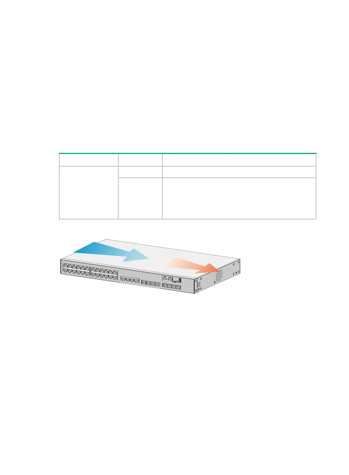
• The S5560X-34S-EI and S5560X-54S-EI switches use fixed fan trays and the airflow direction
is from left to right. (Left and right refer to the directions when you face the port side panel of the
switch.)
• The S5560X-EI switches except the S5560X-34S-EI and S5560X-54S-EI use hot-swappable
fan trays. They provide airflow from the port side to the power module side or from power
module side to the port side by using different types of fan trays. You must install two fan trays of
the same model for each of these switches. See Table 44 for fan tra
ys available for the
switches.
Table 44 Hot-swappable fan trays available for the switches
Device model Fan tray Airflow direction
S5560X-30C-EI
S5560X-54C-EI
S5560X-30F-EI
S5560X-54F-EI
S5560X-30C-PWR-EI
S5560X-54C-PWR-EI
LSPM1FANSA From the power module side to the port side and chassis sides
LSPM1FANSB From the port side and chassis sides to the power module side
Figure 73 Airflow through the switch with fixed fan trays (S5560X-34S-EI)

 Loading...


