18
Installation
3.6 Electrical installation
Refer to the following sections for the communication option that is used:
• RS485 (section 3.6.3 on page 18)
• RS232 (section 3.6.4 on page 20)
• Pulse (section 3.6.5 on page 20)
• Ethernet (section 3.6.6 on page 21)
• Wireless (section 3.6.7 on page 22)
• Analog (section 3.6.8 on page 23)
3.6.1 Wire preparation
Complete the following steps before connecting wires to the terminal blocks.
1. Press the tabs on the sides of the terminal block to open the block.
2. Properly prepare each wire by removing the insulation on the wires by ¼ inch.
3.6.2 Power requirements
DANGER
Electrocution hazard. Do not connect this product directly to an AC power source.
DANGER
Electrocution hazard. The output voltage of the power supply unit for this product
must not exceed 28 VDC.
An external power source that can supply 24 VDC is necessary to supply power to the
instruments. The maximum number of units that can connect to the power source can
change with the communication option. Contact the factory for more information.
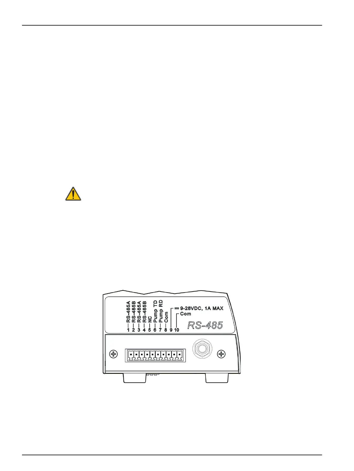
3.6.3 RS485 wiring
Refer to Figure 10 and Table 2 to install a particle counter with RS485 communication.
Figure 10 Terminal assignments—RS485 communication
 Loading...