40
Operation
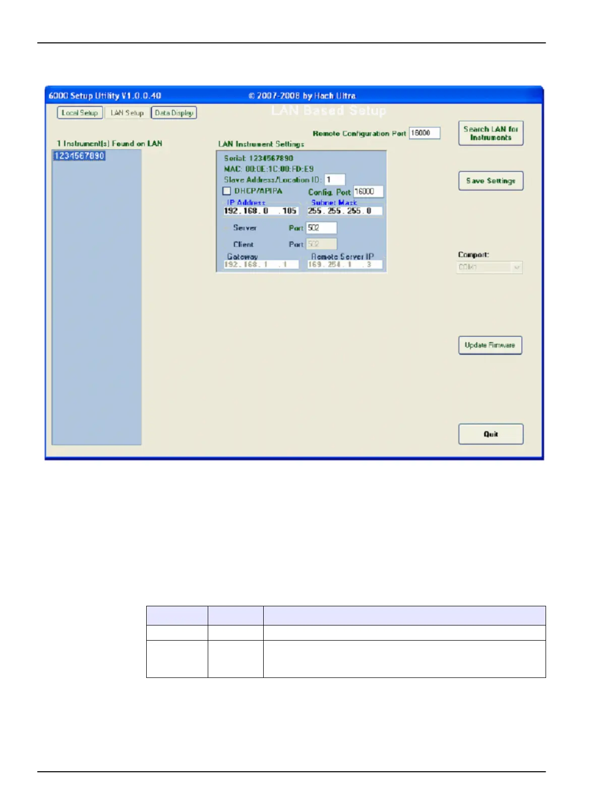
4.3.1.4 Network configuration
Error messages
If an error message such as "Invalid IP setting" is shown, refer to Table 11 to find the
values that can be used. Enter a value in the range for the setting.
4.3.1.5 Wireless LED indicators
Refer to Table 13 for a description of the Ethernet connection LED indicators.
Figure 28 LAN setup for Ethernet units
Table 13 LED indicators for wireless
LED color On/Off Indicator
Green On Internal instrument Ethernet Link is established
Yellow On
Wireless communication is enabled. Occasional blinking indicates
data transfer. High rates of blinking may occur if a Wireless LAN
cannot be found, or the Wireless settings are incorrect.
 Loading...