7
General information
2.3 General product information
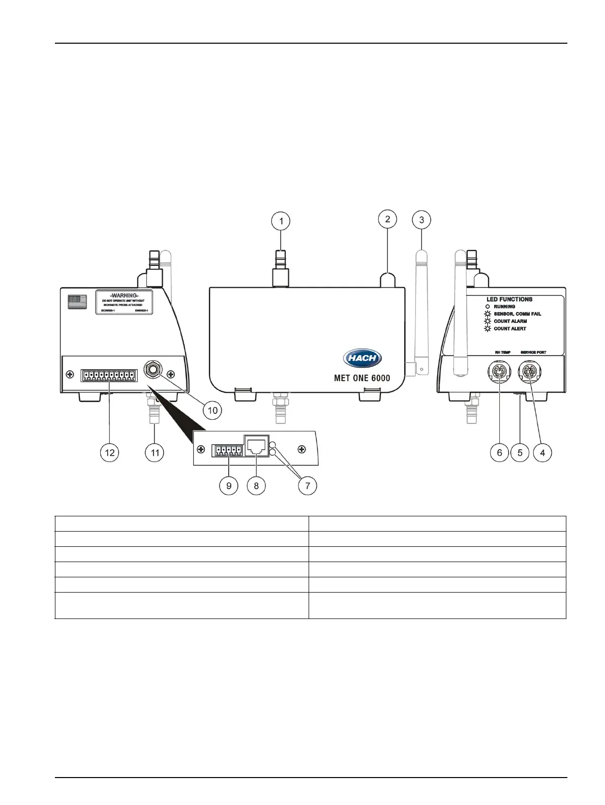
Figure 3 shows a diagram of the Met One 6000 particle counter. The remote airborne
particle counters use a laser diode light source and collection optics for particle detection.
The air quality of a clean room can be monitored by placing multiple particle counters at
specific locations in the room.
The Met One 6000 particle counter has three main components—the sensor, counting
electronics and communication electronics. Room air is pulled through the particle
counter by a vacuum source. The sensor detects the particles that enter the counter. The
counting electronics store the count data. The data is transferred to the central monitoring
software through the communication electronics and relevant communication protocols.
2.4 Status LED indicator description
The particle counter has a multi-color LED indicator (Figure 3) that indicates the status of
the system. The colors indicate normal, alarm, alert or failure (refer to Table 1). The limits
that activate the indicator can be changed using the central monitoring software or the
setup utility (section 4.1.2 on page 30).
Figure 3 Overview of Met One 6000 particle counter
1 Inlet tube fitting, ¼-in. or
1
/8-in. 7 Connection indicators (Ethernet and Wi-Fi units only)
2 Status LED indicator 8 Ethernet RJ45 connector (Ethernet unit only)
3 Antenna (Wi-Fi unit only) 9 5-pin connector for power (Ethernet and Wi-Fi units only)
4 Service port for setup or external indicator light 10 Tube fitting to vacuum (or quick-connect fitting)
5 Dip switch for serial RS485 units only 11 Tube fitting to vacuum, alternate location
6 RH Temp port for temperature/humidity sensor 12 10-pin connector for power and communication (all units
except Ethernet and Wi-Fi)
 Loading...