19
Installation
Network wiring
RS485 (EIA-485) supports up to 32 instruments (12 K load each). Use a high grade wire
for serial communications such as Belden 9841. The manufacturer recommends that the
length of the network does not exceed 1200 meters.
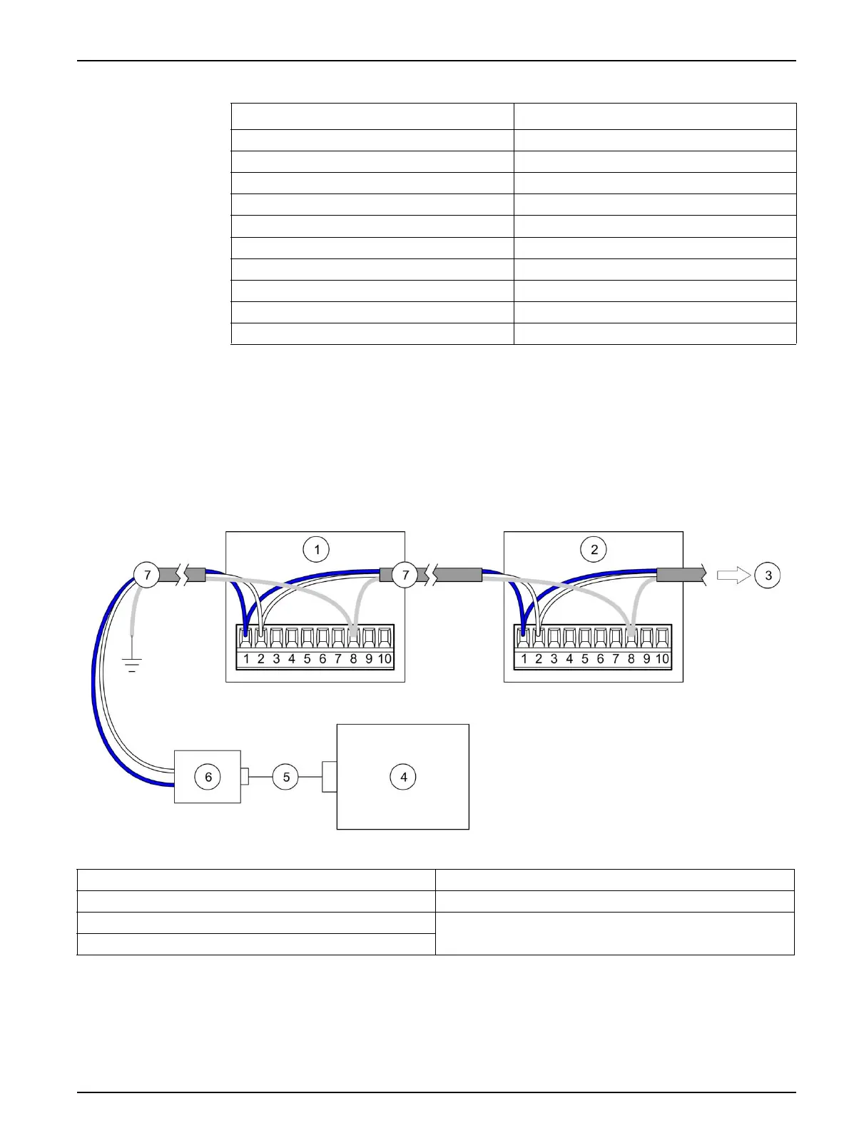
A typical network wiring diagram for the particle counter is shown in Figure 11. Up to 32
remote counters can be in the network using RS485 Modbus or FXB communication.
Table 2 Terminal assignments—RS485 output
Terminal Assignment
1 RS485 A
2 RS485 B
3 RS485 A
4 RS485 B
5NC
6 Pump TD
7 Pump RD
8 Common (shield ground)
9 Power source (9–28 VDC, 1 A maximum)
10 Common
Figure 11 Network wiring—10-pin connector
1 Particle counter 5 Cable
2 Particle counter 6 RS232 to RS485 converter
3 To additional particle counters 7 Network cable
4 PC
 Loading...