3 - Description
3.8
DANGER! Suction SmartValve must always be turned to the unused position and turn the pressure SmartValve to
“Main tank” (both levers pointing forward) before opening the Cyclone filter! If not then spraying liquid can hit you
when opening the filter and drain from the tank!
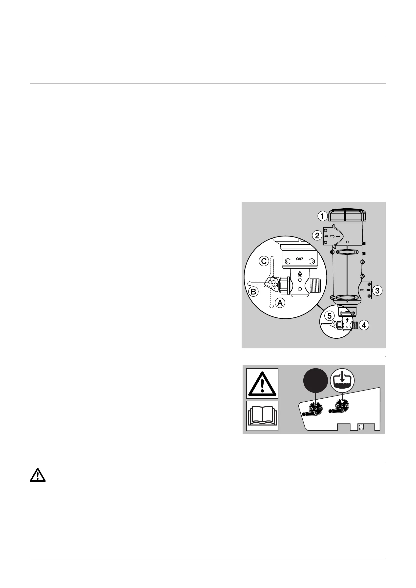
Valve (5) has three positions marked with small dots on the lever:
Position A (Marked with 1 dot): There is no return flow. Position is
used when rinsing the boom if there is spray liquid in the main tank.
Also used when high spraying volume is required.
Position B (Marked with 2 dots): Normal spraying position. With
return flow to prevent filter being clogged when spraying. Position is
used when rinsing the boom if the main tank is empty.
Position C (Marked with 3 dots): Flushing position, used if filter is
clogged. Lift and hold the lever to use this position which largely
increases return flow and cleans the filter.
EFC - Electrical Fluid Control. The ON/OFF is linked to the section valves, which results in a very quick response to
ON/OFF. The operating unit is constructed of modules and is electrically controlled via a remote control box.
A EasyClean suction filter is fitted in the working zone near the Smart Valves. It has a built-in valve that closes when the
filter is opened for inspection or cleaning.
A Cyclone pressure filter is fitted to the sprayers right side just behind the handbrake. It has a built-in self-cleaning
function.
In-line pressure filters can be fitted at each section as an option.
Nozzle filters are fitted at each nozzle.
All filters should always be in use and their function checked regularly. Pay attention to the correct combination of filter
and mesh size. The mesh size should always be less than the flow average of the nozzles in use.
With the CycloneFilter the impurities that exist in the spray liquid will
by-pass the filter and be recirculated back to the tank via the return
flow.
Function diagram
1. Filter lid
2. From pump
3. To boom
4. Return to tank
5. Return valve
CycloneFilter
Filters
Section control unit
 Loading...