4 - Sprayer setup
4.8
ATTENTION! Tractor drivers seat is the intended working place
during operation.
Connect plug for rear lights to the tractor’s 7-pin socket, and check function of rear lights, stop lights and direction indi-
cators on both sides before driving.
The wiring is in accordance with ISO 1724. See section in “Technical specifications”.
Before transport on public roads the front warning boards with position lamps must be folded out (fitted in certain coun-
tries only).
Find a suitable place in the tractor’s cabin. Best recommended pla-
cement is to the right of the driver seat and in combination with the
SPRAY control box. It should be secured from movement.
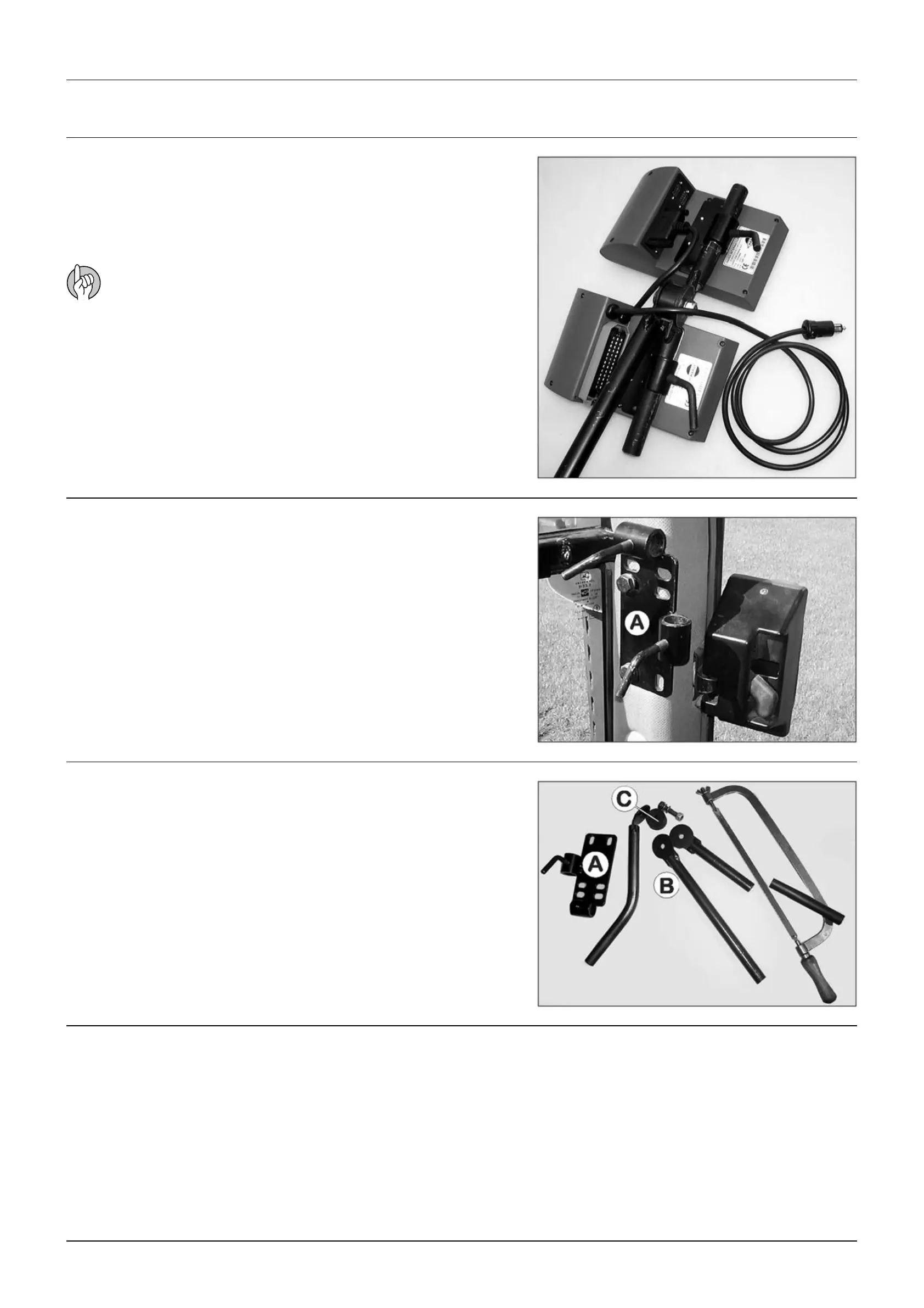
The supplied tractor pillar bracket (A) has a hole spacing of 100 and
120 mm. Check tractor instructions manual for information regar-
ding attachment points.
Three tubes (B) are supplied. One, two or all 3 may be used. They can
be bent and shortened. A spacer (C) is also supplied to allow further
attachment possibilities. Find the best solution for your tractor or
vehicle.
Tube (B) plate is staggered so if correctly orientated, all boxes will
line up.
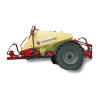
Find a suitable place in the tractor’s cabin. Best recommended pla-
cement is to the right of the driver seat and in combination with the
Hydraulics control unit. It should be secured from movement.
Road safety kit
Installation of control unit brackets
Installation of control box - Hydraulics control unit
Installation of control box - EFC control unit
Electrical connections
 Loading...