APEX™ Exciter Incorporating FLO™ Technology
Theory of Operation APEX Exciter Digital Assembly Overview
Page: 4-2 888-2604-001 03/08/07
WARNING: Disconnect primary power prior to servicing.
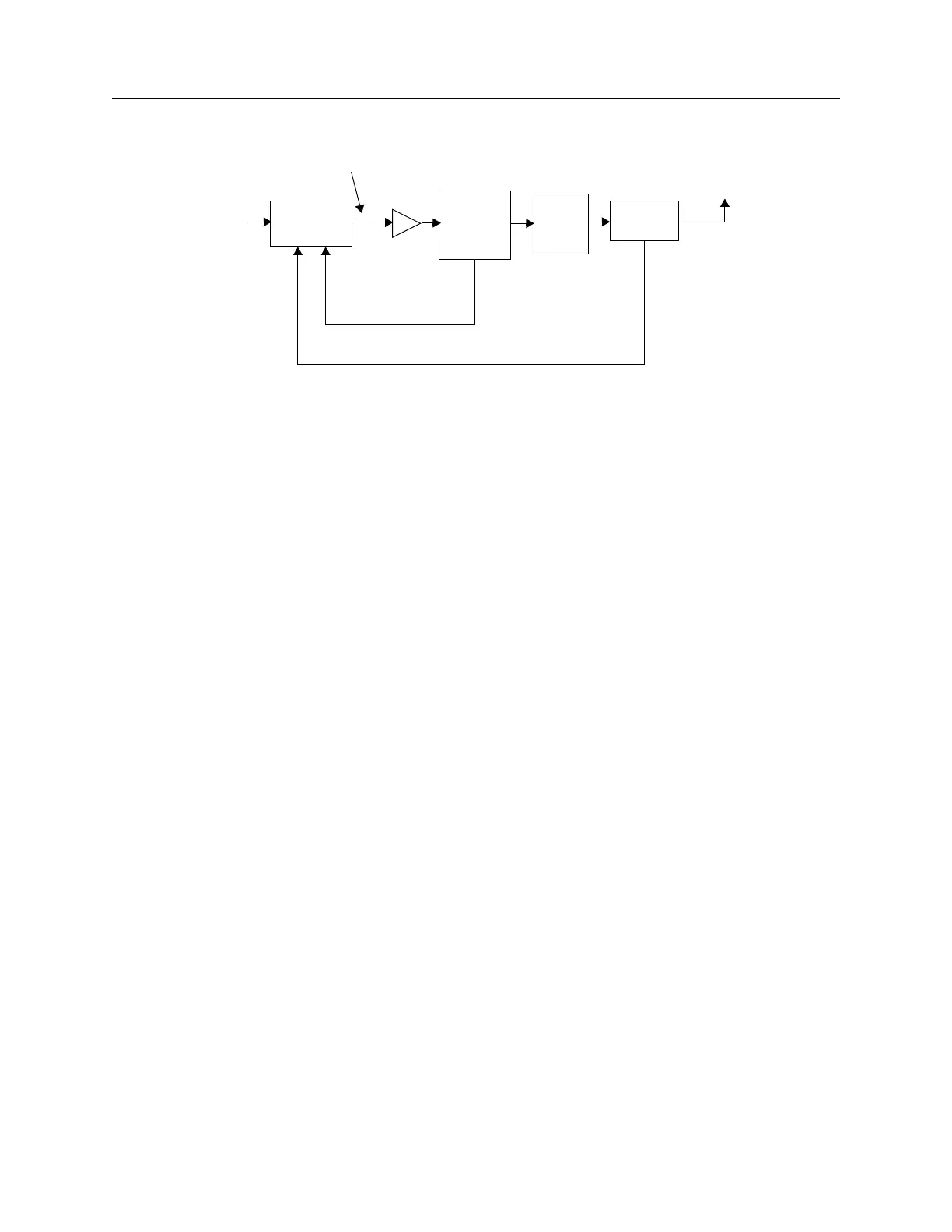
Figure 4-1 APEX Exciter/ Transmitter - RF Interconnection Block Diagram
4.3 APEX Exciter Digital Assembly Overview
Figure 4-2 is an overall block diagram of the APEX exciter. Refer to it while studying the
exciter digital assembly, also, refer to Figure 5-2, on page 5-3 for a view of the physical
layout digital tray.
The APEX exciter digital assembly (bottom side of exciter) accepts dc supply voltages
from the power supply board (located in the top, analog side of the exciter) and an ASI
transport stream as input. This tray provides a fully modulated OFDM (orthogonal
frequency division multiplexed) first IF output centered at 11.1 MHz.
The digital assembly also performs RTAC™ (real time adaptive correction) pre-correction
on the signal following the modulation and spectral filtering processes. Two down
converted samples from various locations along the transmitter system are compared the
output of the modulator board to shape the pre-corrected RF output signal of the exciter.
This pre-corrected signal minimizes the nonlinear and linear distortions of PA and high
power filter.
The digital assembly consists of 6 circuit boards:
• A7 - UHF External I/O (input/output) Board
• A8 - Controller Board
• A9 - Adaptive Precorrector board
• A11 - ADC (analog to digital converter) board
• A12 - DAC (digital to analog converter) board
• A13 - FPGA Modulator board
Signal flow from input to output of the digital (bottom) assembly of the exciter may be
followed by referring to Figure 4-2. The ASI transport stream is input to the FPGA
Modulator board, A13.
The modulator board output passes through the controller board (A8) and on to the
adaptive precorrector board (A9).
PA
Output
Coupler
High
Power
PA
Cabinet
Filter
Coupler
APEX
Exciter
RF output
to Antenna
PA (Non-Linear)
RF Feedback Sample
HPF Output (Linear)
RF Feedback Sample
Transport
Stream
Input
Exciter RF
Output