APEX™ Exciter Incorporating FLO™ Technology
Details of the Exciter Status Screens Navigating the LCD Display Screens
2604s300.fm
03/08/07 888-2604-001 Page: 3-11
WARNING: Disconnect primary power prior to servicing.
3.4.3.1 Adaptive Processing Diagnostics
AdaptPrecDiagnostics.bmp
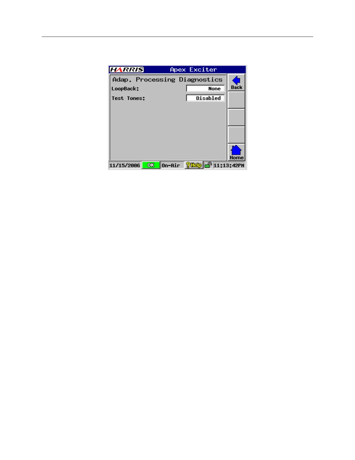
Figure 3-8 Adaptive Processing Diagnostics
The Adaptive Processing Diagnostic screen is shown in Figure 3-8, with screen entries
listed below.
• loopback: Selections include None, Analog, or Digital.
None is the normal mode.
Digital loops the D/A converter input bit stream back to replace the A/D converter
output bit stream. It tests the modulator and corrector boards.
Analog loops the 11.1 MHz IF output from the D/A board to the IF input of the A/D
board via an existing RF cable jumper. It tests the A/D and D/A converters.
Results of the digital or analog loopbacks can be viewed on the Main screen re-
sponse display by setting the Setup > Display Setup Chart Source selection to ex-
citer.
• Test Tones: (Disabled or Enabled) Disabled is normal mode. Enabled turns on two
test tones, which are used as built in functions for inter modulation tests. It is used by
factory final test and field service. When enabled, this function mutes the exciter, the
signals are visible within the exciter.