APEX™ Exciter Incorporating FLO™ Technology
Installation Installation of the GPS 1PPS Signal
Page: 2-2 888-2604-001 03/08/07
WARNING: Disconnect primary power prior to servicing.
• PA SAMPLE IN (SMA) is the input signal connector for an RF sample from the out-
put of the transmitter power amplifier, taken before the HPF and after the PA combin-
er for transmitters with multiple PAs. It is used by RTAC™ to correct for the
nonlinear distortion caused by the power amplifier. Normal input signal range is -30
dBm to 0 dBm. The input impedance is 50 ohms.
• IPA SAMPLE IN (SMA), not used
• RF OUT (SMA) is the on-channel RF signal output from the exciter. Output level is
adjustable up to 250 mW average.
• EXC/CTRL UHF (25 Pin D) is the exciter control interface connector used to connect
the UHF version of the exciter to the transmitter and the exciter switcher.
• CAN (controller area network) is a provision for the exciter to communicate with the
transmitter GUI (graphical user interface) system controller.
• LAN 10Base-T is a provision for connecting the exciter to a local area network.
• RS232 (on front and rear panels of exciter) is a 9 Pin D interface connector. They are
used to communicate with various computer applications. The front and rear panel
connections can be programmed and used independently of each other.
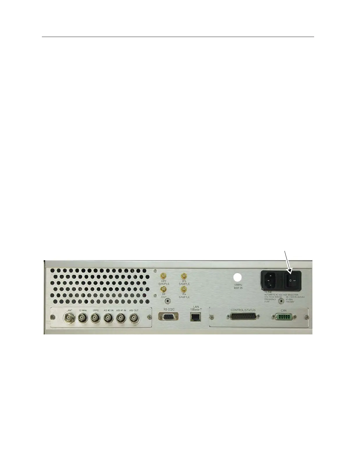
2.3.1 AC Power
AC Power is applied through a standard power cord to the connector at the right side of the
rear panel as shown in Figure 2-1. The AC inlet connector also contains the power switch.
The power supply will automatically select the AC input voltage in two ranges. The two
ranges are 85 to 132 VAC or 170 to 264 VAC
Figure 2-1 Exciter Inputs and Outputs
2.4 Installation of the GPS 1PPS Signal
The GPS (global positioning system) 1PPS (1 pulse per second) signal has a rise time in the
order of a few nanoseconds. It is delivered by a 50 ohm transmission line to the exciter.
Improper termination can cause ringing on the pulse, which, if severe enough can cause
timing errors in the system. The 1PPS signal must be properly distributed and terminated
to avoid the ringing problem.
Figure 2-2 shows two methods of distributing the 1PPS signal.
AC Power
Off/On Switch