APEX™ Exciter Incorporating FLO™ Technology
Navigating the LCD Display Screens Details of the Exciter Status Screens
Page: 3-20 888-2604-001 03/08/07
WARNING: Disconnect primary power prior to servicing.
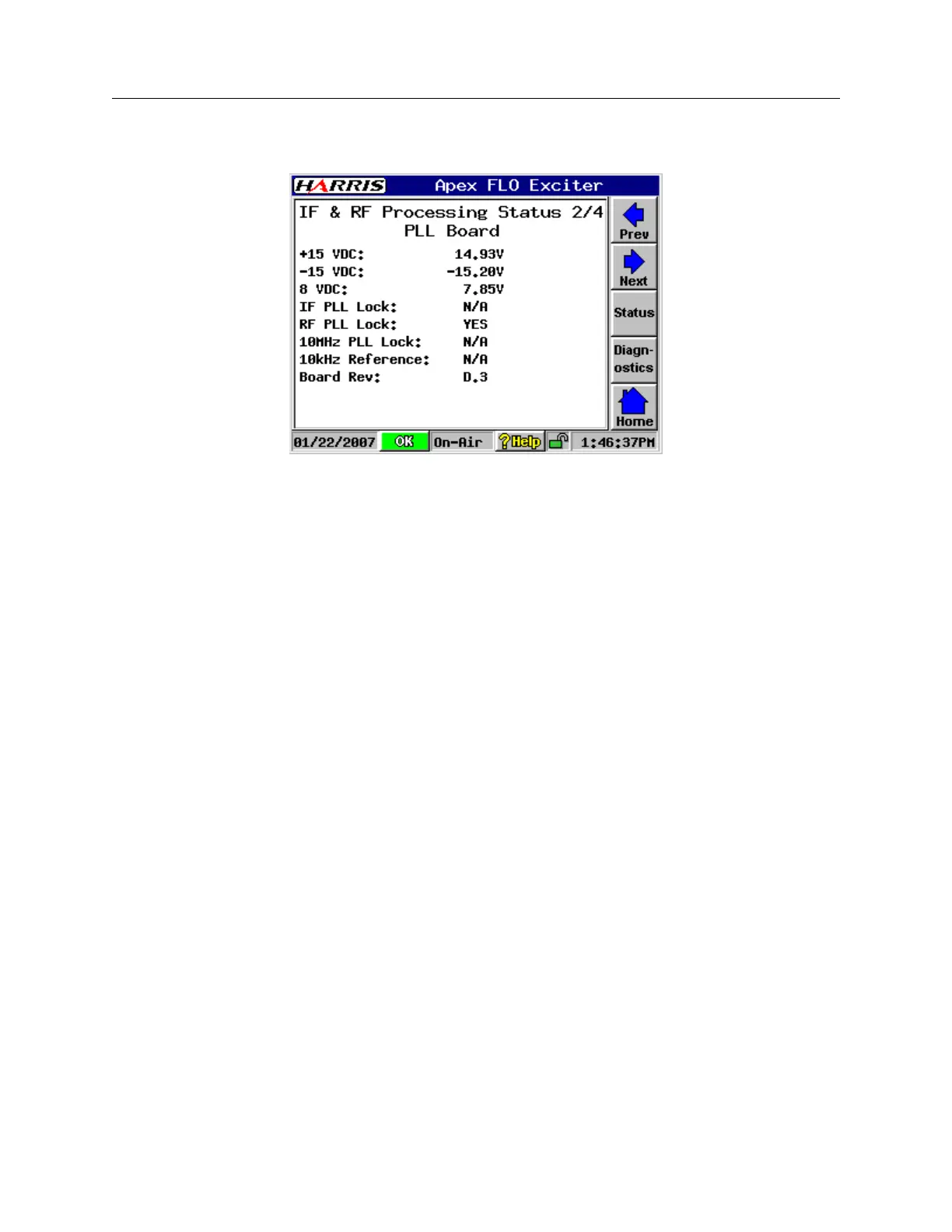
3.4.5.2 PLL Board Status Screen
PLLStatus.bmp
Figure 3-18 PLL Board Status Screen
The PLL Board screen is shown in Figure 3-18, with screen entries listed below.
• 15 Vdc: Input power from UDC interface board via connector J1.
• -15 Vdc: Input power from UDC interface board via connector J1.
• 8 Vdc: Input power from UDC interface board via connector J1.
• IF PLL Lock: (YES or NO) This PLL should normally be locked.
• RF PLL Lock: (YES or NO) This PLL should normally be locked.
• 10MHz PLL Lock: (N/A) The PLL board 10 MHz oscillator frequency is now refer-
enced to the external 1PPS GPS signal via the FPGA board and the PLL board DAC.
• 10 kHz. Reference: (N/A) This input is no longer used to lock the PLL board 10 MHz
oscillator.
• Board Rev: This is the board revision for the PLL board.