APEX™ Exciter Incorporating FLO™ Technology
Details of the Exciter Status Screens Navigating the LCD Display Screens
2604s300.fm
03/08/07 888-2604-001 Page: 3-15
WARNING: Disconnect primary power prior to servicing.
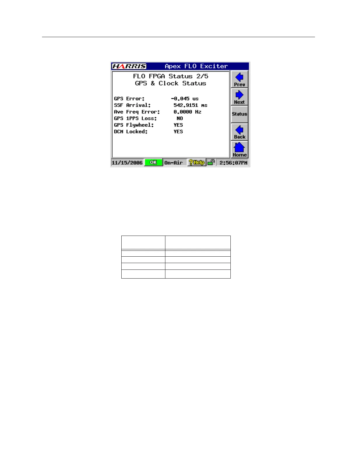
3.4.4.4 FLO FPGA, GPS & Clock Status, Screen 2/5
FPGA Status2.bmp
Figure 3-13 FLO FPGA, GPS & Clock Status, Screen 2/5
The parameters of the FPGA GPS & Clock Status screen are as follows.
• GPS Error: The value for GPS Error is displayed in microseconds. It is calculated
from the GPS error register based on the bandwidth selected, as show in the table be-
low:
• SSF Arrival: displayed in milliseconds
• Ave Frequency Error: In Hz
• GPS 1PPS Loss: YES (in red) indicates loss of GPS 1PPS, NO (in black) indicated
signal is present.
The indication will change to YES and cause the exciter to mute after the GPS has
been missing long enough to exceed 1PPS Mute Delay.
The 1PPS Mute Delay time out setting is found on the Main Screen > Setup > FLO
FPGA > FPGA Configure 2/5 screen.
• GPS Flywheel: YES indicates GPS Flywheel is operational, NO indicated Flywheel
not present.
• DCM Locked: YES indicates lock, NO indicated unlock.
Bandwidth
GPS Error Displayed
Value (uS)
5 MHz Register value / 37.0
6 MHz Register value / 44.4
7 MHz Register value / 51.8
8 MHz Register value / 59.2