APEX™ Exciter Incorporating FLO™ Technology
Details of the System Setup Screens Navigating the LCD Display Screens
2604s300.fm
03/08/07 888-2604-001 Page: 3-35
WARNING: Disconnect primary power prior to servicing.
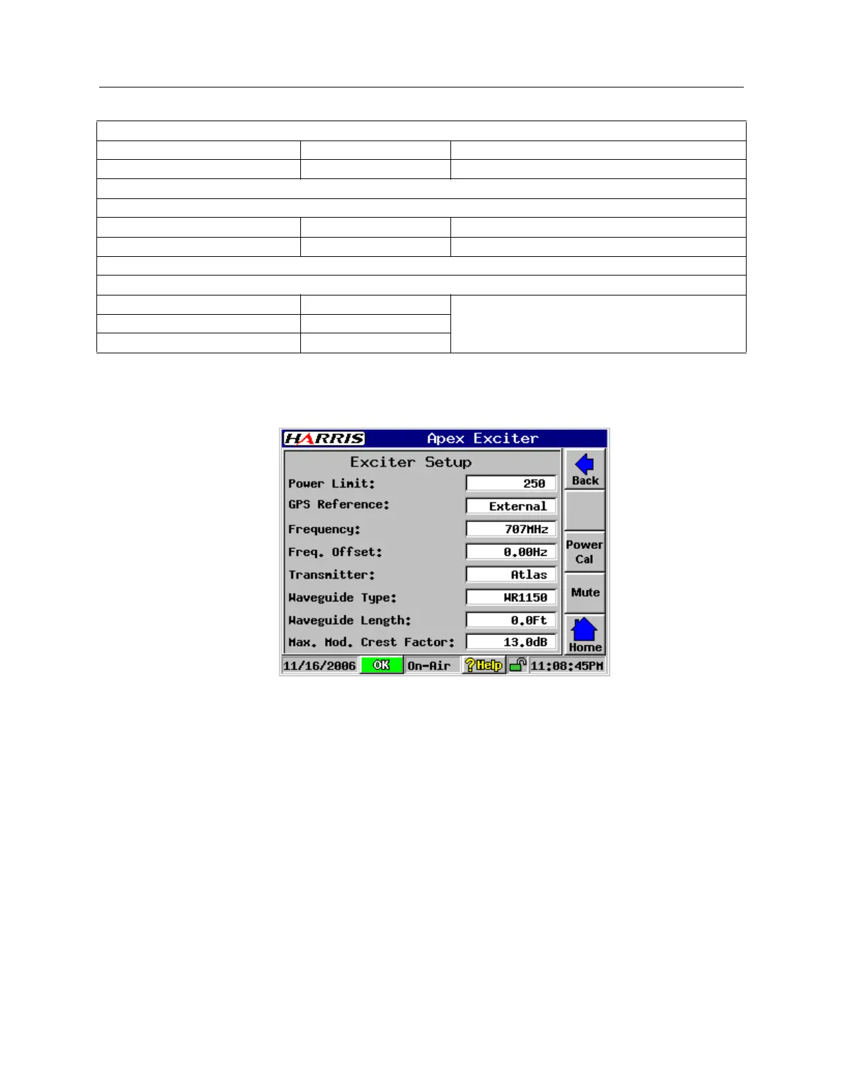
3.6.2 Exciter Setup Screen
ExciterSetup.bmp
Figure 3-32 Exciter Setup Screen
Refer to Figure 3-32, Exciter Setup Screen. The following ia a list of entries on the Exciter
setup screen.
• Power Limit. This adjustable S/W power limit will act as a clamp and will not allow
the user to set the power above this limit either locally on the exciter main screen or
remotely via the external I/O board raise/lower input. The range of this control is 0 to
250 mW.
• GPS Reference, refers to External or Internal GPS receiver use.
External is the normal mode. If used, it requires an external 1PPS input at the rear
panel connector.
Loss of the 1PPS will cause a Digital Status hardware switch fault (lights red) and the
Main Screen > Status > Digital Processing > FLO FPGA Registers will show fault.
Down Converter Status Diagnostics, See Section 3.4.5.4.1, Down Converter Diagnostics, on page 3-24
RF Sample Select Automatic Normal
RF Sample AGC Enabled Normal
Controller Status Diagnostics, See Section 3.4.6.1.1, Controller Board Diagnostics, on page 3-26
BIT Fifo Test Pattern Disabled Normal
DSP/FPGA S/W Watchdog Disabled Normal
External I/O Status Diagnostics, See Section 3.4.6.2.1, External I/O Diagnostics, on page 3-28
Analog Loopback Disabled Normal, but can be useful for analog input and
output testing, see technical manual.
Analog Output A 0
Analog Output B 0
Table 3-3 Settings Resulting From Restore Defaults Activation.