Chapter 1
Introduction
8
Copyright © 2010, Harris Corporation
DA-HRO6804+D
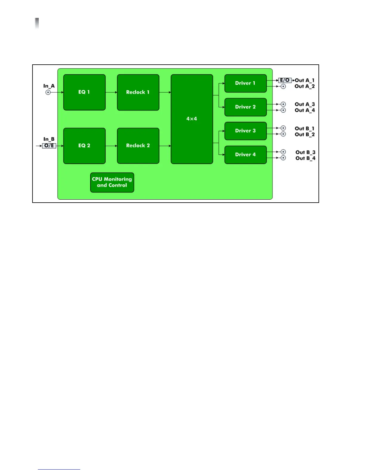
The main features for the DA-HRO6804+D are listed below. Figure 1-5 shows a
basic signal flow diagram for this distribution amplifier module.
Figure 1-5 DA-HRO6804+D Signal Flow Diagram
Operates with dual slot, RT optical distribution amplifier back module (see
page 14)
Passes signals at data rates from 5 Mb/s to 3 Gb/s
Three selectable channel configurations:
1×8_ACO: 1 electrical input to 1 optical output and 7 electrical outputs
with auto changeover
The Electrical signal on SDI In_1 is distributed to 1 optical output and 7
electrical outputs. If the electrical signal at SDI In_1 disappears, the
outputs are switched to Optical input at SDI In_2 (if an Optical signal at
SDI In_2 is detected). When the Electrical signal reappears on SDI In_1, the
outputs are automatically switched back to SDI In_1 from SDI In_2.
1×8_ In_1: 1 electrical input (In_A) to 1 optical output and 7 electrical
outputs
1×8_ In_2: 1 optical input (In_B) to 1 optical output and 7 electrical
outputs
Input signal presence detect and report
Optical input status for optical input (by CCS)
Automatic input cable equalization for electrical input
Selectable +6 dB gain to use external passive 75 2×1 splitter (via CCS only)
for electrical input
Selectable input EQ bypass for electrical input
Reclockable for 270 Mb/s, 1.485 Gb/s, or 2.97 Gb/s SMPTE and DVB-ASI
signals
Three selectable reclocking modes (automatic, manual, enforce bypass)