DA-6804+D Series
Installation and Operation Manual
21
Copyright © 2010, Harris Corporation
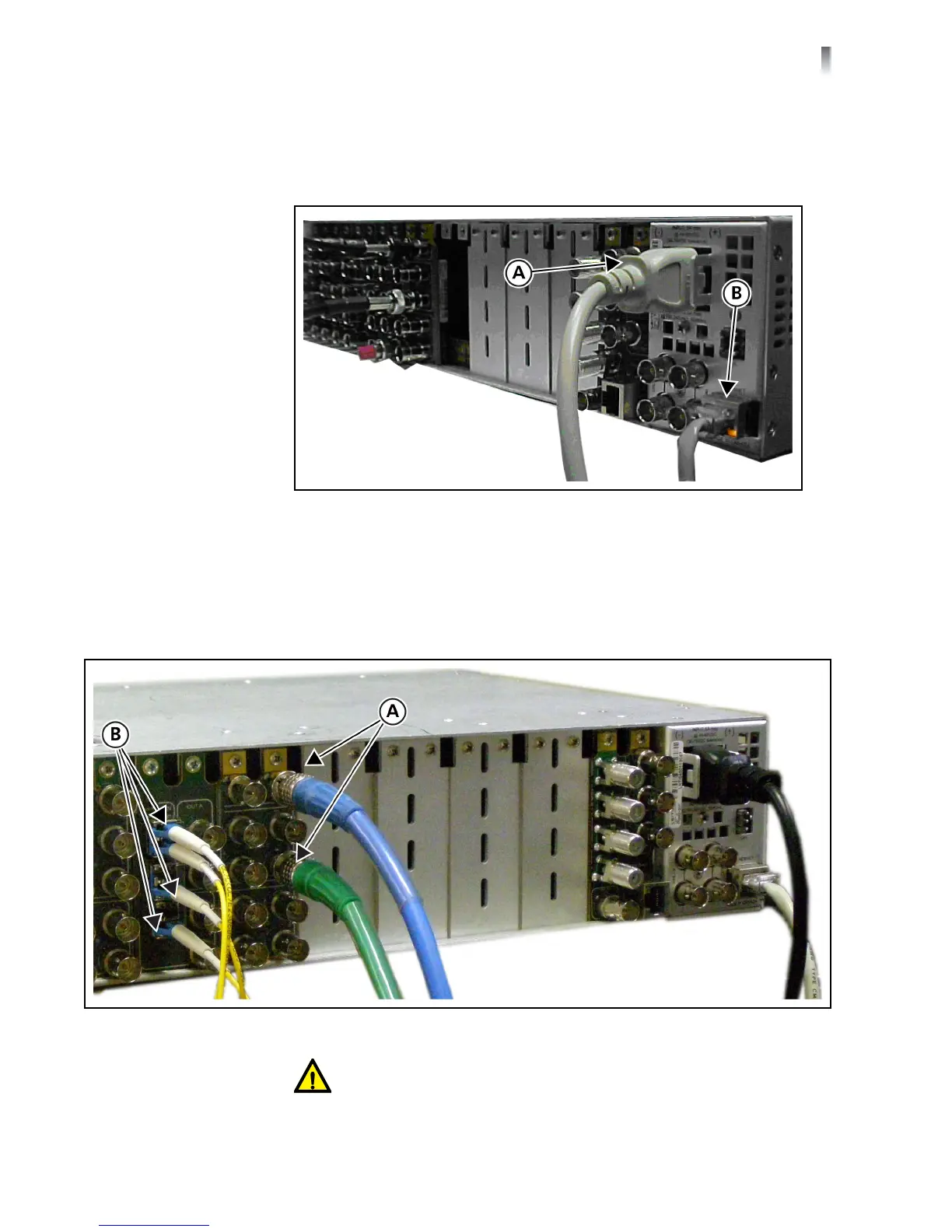
If the frame uses CCS control, plug the power cord (A) and the Ethernet connector
cable (B) to the back of the frame, as shown in Figure 2-2. Plug the other end of
the power cord into an electrical outlet. Plug the other end of the Ethernet
connector to a PC that has Harris CCS software installed.
Figure 2-2 Connection for CCS Control
Setting Up Back
Connector
Modules
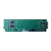
Back module setup consists of plugging in coaxial cables (A) and fiber optical
cables (B), as shown in Figure 2-3. Apply a 75 coaxial cable to the BNC jacks and
LC single mode fiber optical cables, as appropriate, to installed back modules. The
other ends of the cables should be connected to a system’s other devices.
Figure 2-3 Plugging in Coaxial and Fiber Optical Cables
CAUTION: Take special care when attaching fiber optical cables. See
page 21 for more information.