Chapter 2
Installation
22
Copyright © 2010, Harris Corporation
Setting Up Front
Modules
Front module setup consists of setting the jumpers for the DA-6804+D series
modules. Three jumpers that need to be set: J1 and J2 are used for reclockers, and
J3 is designed for channel configuration and enabling remote control.
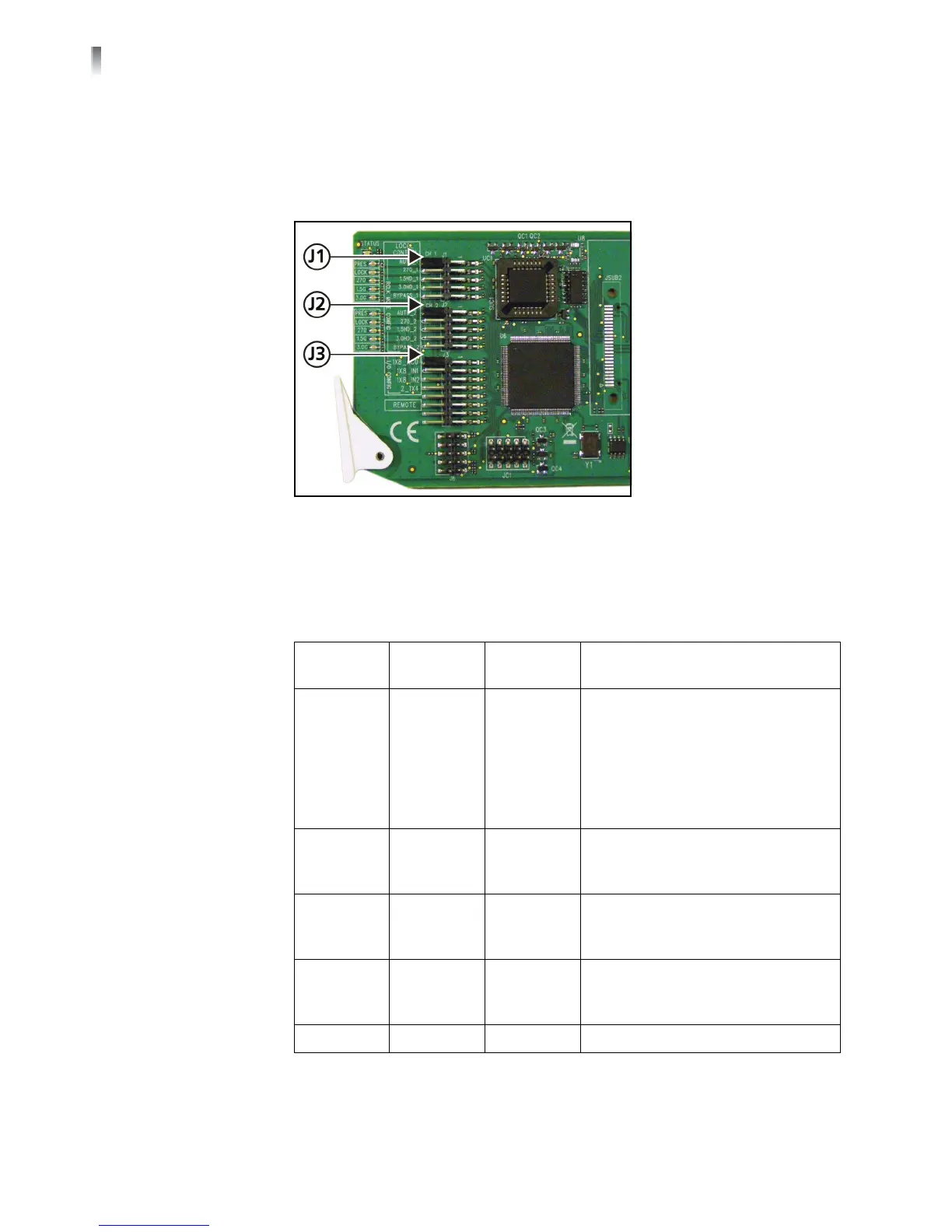
Figure 2-4 shows the location of the J1, J2, and J3 jumpers.
Figure 2-4 Jumper Locations
Setting Up J1 and J2
Jumpers
J1 and J2 are used to locally set the reclocker working mode. J1 is used for
channel 1 and J2 for is used for channel 2. The reclocker remains in AUTO mode if
no shunt is on any position of the jumper.
Table 2-2 J1 and J2 Jumper Settings
Jumper
Selection
Pin
Setting
Label Description
J1/J2 1/2 AUTO_1/2 Input signal locked at one of these
data rates:
2.97 Gb/s
1.485 Gb/s
270 Mb/s
If not relockable, signal automatically
bypasses reclocker
J1/J2 3/4 3.0G_1/2 Input signal locked at 2.97 Gb/s
*
;if
not relockable, signal automatically
bypasses reclocker
*
Not used with DA-DSR6804+
J1/J2 5/6 HD_1/2 Input signal locked at 1.485 Gb/s
*
;if
not relockable, signal automatically
bypasses reclocker
J1/J2 7/8 SD_1/2 Input locked at 270 Mb/s; if not
relockable, signal automatically
bypasses reclocker
J1/J2 9/10 BYPASS_1/2 Enforces signal bypass reclocker