Chapter 3
Operation
28
Copyright © 2010, Harris Corporation
LED Displays
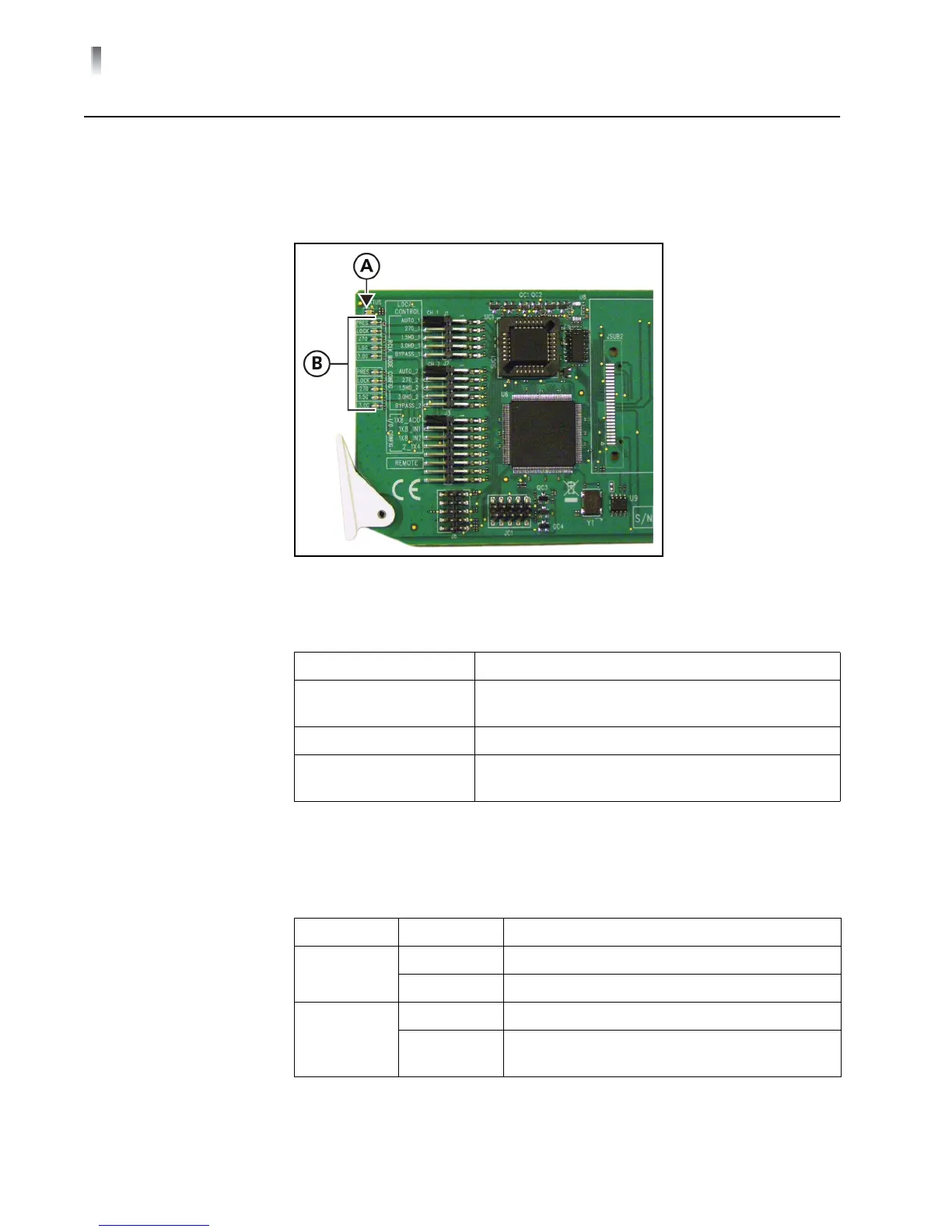
LEDs on the front edge of the front module report the operating status when
power is ON and signal is applied. The location of the system status (A) and signal
condition (B) LEDs are shown in Figure 3-1. The meaning of the system status LED
color sequence is described in Table 3-1. The meanings for the signal condition
LEDs are described in Table 3-2.
Figure 3-1 LED Locations
System Status
Indicators
Signal Condition
Indicators
Each 6800+ module has a number of LEDs assigned to indicate varying states/
functions. These functions are listed in Table 3-2.
Table 3-1 System Status Indicator LED Descriptions
LED Color Sequence Meaning
Off There is no power to the module; the module is not
operational
Red There is an alarm condition
Green There is power to the module; the module is
operating properly
Table 3-2 Signal Condition LED Descriptions
Name Color Function
PRES Green Input signal is present
Off Input signal is absent
LOCK Green Input signal is locked
Off Input signal is unlocked and appears on the
outputs