15
PME-MP55
HBMA0563-5.5 en
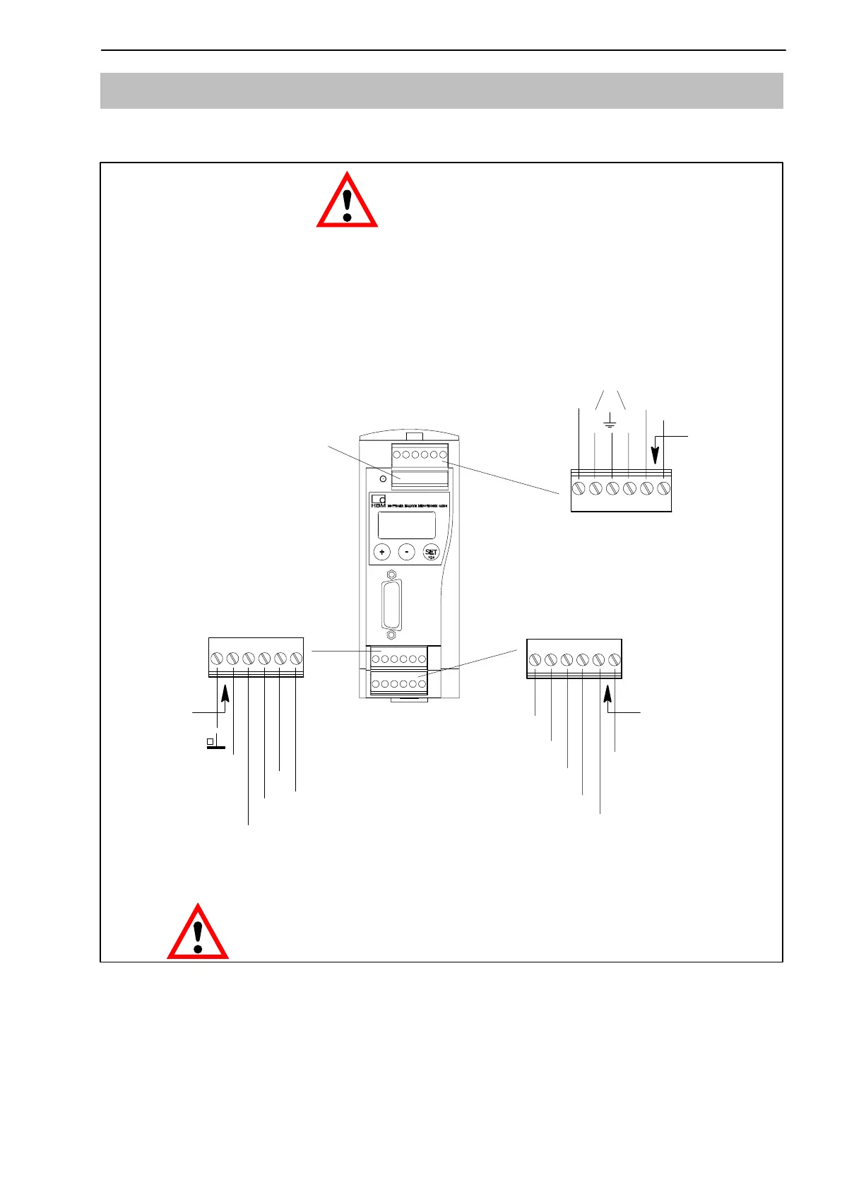
4.2 Supply voltage and remote contact I/Os
Four removable terminal plugs are available for connections.
0 V
SYN
Analogue-
OUT
"10 V
"20 mA
4...20 mA
IN1
IN2
IN3
IN4
0 V
24 V
OUT1
OUT2
OUT3
OUT4
Terminal plug 3
Terminal plug 4
LH
Terminal plug 1
Connecting the power
supply:
The MP55 module must be connected to an external
18-30 V supply voltage (24 V
nominal
).
Warning
D Twist the power supply conductors and fit them with
sleeves.
D Screw the conductors to terminal plug 1.
D
Insert the terminal plug into the uppermost jack.
D Switch on power supply.
IN = digital input OUT = digital output
More information on I/Os can be found in chapter 6, page 35.
CAUTION
In the event of a power failure to the MP55 module, all control
outputs are set to 0 V.
24 V
Labeling
Labeling
Labeling
Terminal plug 2
CAN
Fig. 4.2: Pin assignment for terminal plugs
The 4 terminal plugs are coded so that they can be inserted in the 4 jacks
without any confusion. Jacks are fitted with coded lateral guides and terminal
plugs are fitted with coded pins.
Artisan Technology Group - Quality Instrumentation ... Guaranteed | (888) 88-SOURCE | www.artisantg.com