24
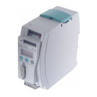
PME-MP55
HBM A0563-5.5 en
5.2 Commissioning
D Set up the DIP switches in accordance with chapter 2 (pages 10 and 11).
Example:
Transducer type and rated data Bridge type Bridge excitation
voltage
Input range
Strain gauge force transducer
2 mV/V=20 kN
Full bridge 5 V 3 mV/V
Inductive displacement transducer 80 mV/V Half bridge 2.5 V 100 mV/V
Inductive displacement transducer 10 mV/V Half bridge 1 V 15 mV/V
Piezoresistive transducer 400 mV/V Half bridge 1 V 250 mV/V
Potentiometric transducer 1000 mV/V Half bridge 2.5 V 1000 mV/V
D Connect the power supply cable and the transducer to the module, as
described in chapters 4.2 and 4.3.
CAUTION
Be sure to follow the safety instructions!
D Switch on the power supply.
The instrument carries out a function test (approx. 15 sec) and if
functioning correctly, switches to measuring mode. During the function
test, the remote contacts stay at 0 V.
NOTE
If the error message HardwOvf is displayed at this point, please refer to
chapter 8 ”Error messages” for more details.
A green LED also tells you whether the MP55 is ready to begin measuring.
If the LED shows yellow or red, please refer to chapter 8 ”Error messages” for
more details.
NOTE
When connecting transducers in parallel, please take into account the
resulting total resistance. If required, reduce the excitation voltage.
Artisan Technology Group - Quality Instrumentation ... Guaranteed | (888) 88-SOURCE | www.artisantg.com