18
PME-MP55
HBM A0563-5.5 en
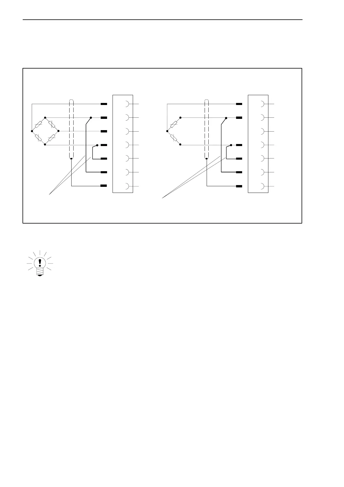
When installing a transducer with a four-wire connection, you must connect
the sensor lines with the corresponding bridge excitation line (Pin 5 with Pin
12, Pin 6 with Pin 13)
1)
.
Wiring colours: wh= white; bk= black; bu= blue; re= red; ye= yellow; gn= green; gy= grey
8
5
6
15
Hsg
.
13
12
wh
bk
re
bu
ye
Feedback bridges for four-wire connection
Four-wire connection:
Full bridge
8
5
6
15
Hsg
.
13
12
wh
bk
gn
bu
ye
Four-wire connection:
Half bridge
gy
Fig. 4.5: Four-wire transducer connection
NOTE
Use standard HBM cable for the transducer connection. When using
other shielded, low-capacitance measuring cable, connect the trans-
ducer cable shielding to the connector housing in accordance with the
HBM Greenline concept (publication S1578). This ensures EMC protec-
tion.
1)
For cable lengths in excess of 50 m, one resistor with half the value of the bridge resistance (R
B
/2) must
be switched on at the transducer in place of each of the feedback bridges. If the transducers are cali-
brated in six-core circuit, the resistors must be switched on directly in the sensor circuit.
Artisan Technology Group - Quality Instrumentation ... Guaranteed | (888) 88-SOURCE | www.artisantg.com