Modules and transducers
Quantum
X
I3031-14.0 HBM: public 99
1
4
5
11
15
Bridge
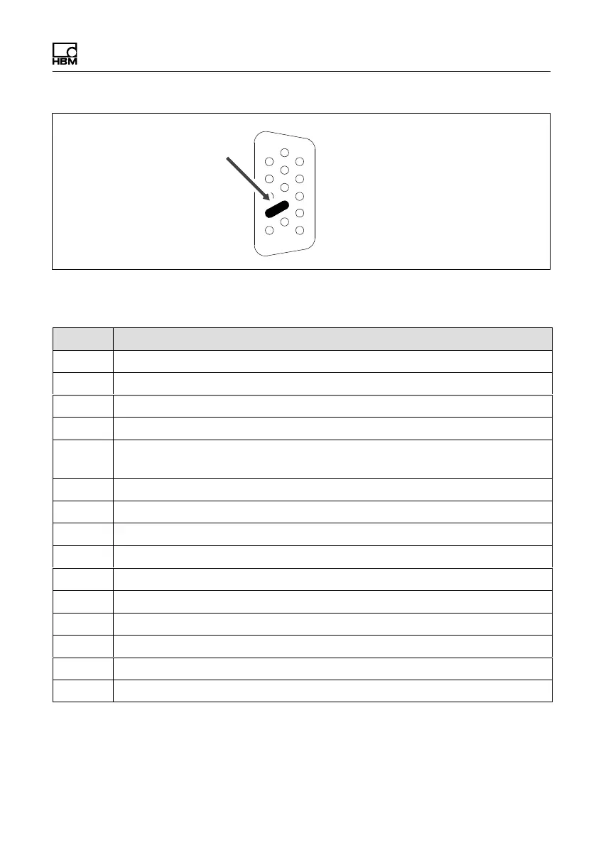
Fig. 8.2 Pin arrangement of connector plug, view from the
solder side
Pin Connector
1 TEDS (+)
2 Bridge excitation voltage (-), 0-reference pulse (zeroing pulse) (-)
3 Bridge excitation voltage (+), 0-reference pulse (zeroing pulse) (+)
4 Always connect with Pin 9! (Plug-in detection)
5 Measurement signal (+), potentiometer measurement signal (+),
voltage input 100 mV (+), f
1
(-) signal differential, SSI data (-)
6 TEDS (-), ground frequency measurement
7 Sense lead (-), f
2
(-) signal differential, CAN-High, SSI clock (-)
8 Sense lead (+), f
2
(+) signal differential, CAN-Low, SSI clock (+)
9 Signal ground
10 Measurement signal (-), f
1
(+) signal differential, SSI data (+)
11 Active sensor supply 5 ... 24 V (0 V)
12 Active sensor supply 5 ... 24 V (+)
13 Current input "30 mA (+)
14 Voltage input 10 V (+), 60 V (+)
15 Digital output