2 Setting up a system
MX Modules A04089_07_E00_02 HBM: public 19
1-CASEMOUNT2-2 and 1-CASEMOUNT3-2
Instructions
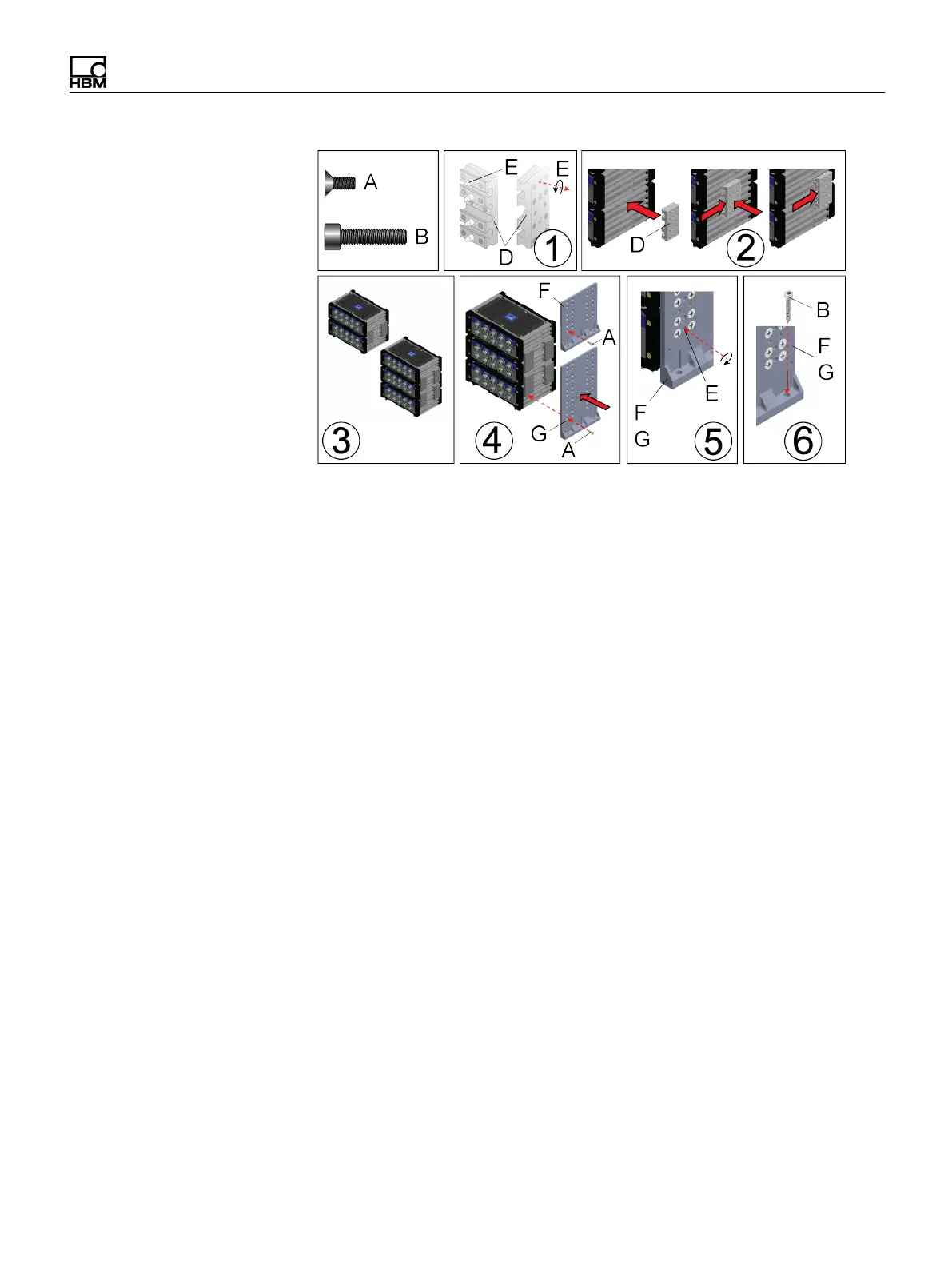
Assemble a stack before applying serviceable (blue) threadlock to Phillips head
screws.
1. Apply serviceable (blue) threadlock to the four (4) M5 set screws (E) in each
caselink (D). Use a 2.5 mm hex wrench to turn set screws back in the caselink
before installing the caselink on a module.
2. Connect two (2) stacked modules by inserting two (2) caselinks (D) in the slots
on each end of the modules.
3. A set of four (4) caselinks can hold two (2) stacked modules together. Kit 1-
CASEMOUNT2-2 includes 1-CASELINK-RUG-2 for two (2) modules. Kit 1-
CASEMOUNT3-2 includes 1-CASELINK-RUG-2 for three (3) modules.
4. Connect a bracket (F or G) to the caselinks using M5 flat screws (A),
serviceable (blue) threadlock and a #2 Phillips screw driver. Apply serviceable
threadlock and tighten each screw until secure using a #2 Phillips screw driver.
5. Tighten the set screws (E) in each caselink using a 2.5 mm hex wrench.
Tighten the screws to 3.6 N-m (32 in-lbs) torque.
6. Install brackets (F or G) on modules and verify measurements before drilling
and tapping holes (M6 18-8 1.0 pitch). The Mounting diagram below is not at 1:1
scale. The dimensions can be used as a guide to tap the holes. The mounting
holes in the brackets area slightly oversized to allow for assembly tolerances.
Apply serviceable threadlock to M6 screws (B) and install them through the
three (3) holes in each bracket (F or G) and into the tapped holes. Tighten the
screws to 6.1 N-m (54 in-lbs) torque.