4 Modules
42 A04089_07_E00_02 HBM: public MX Modules
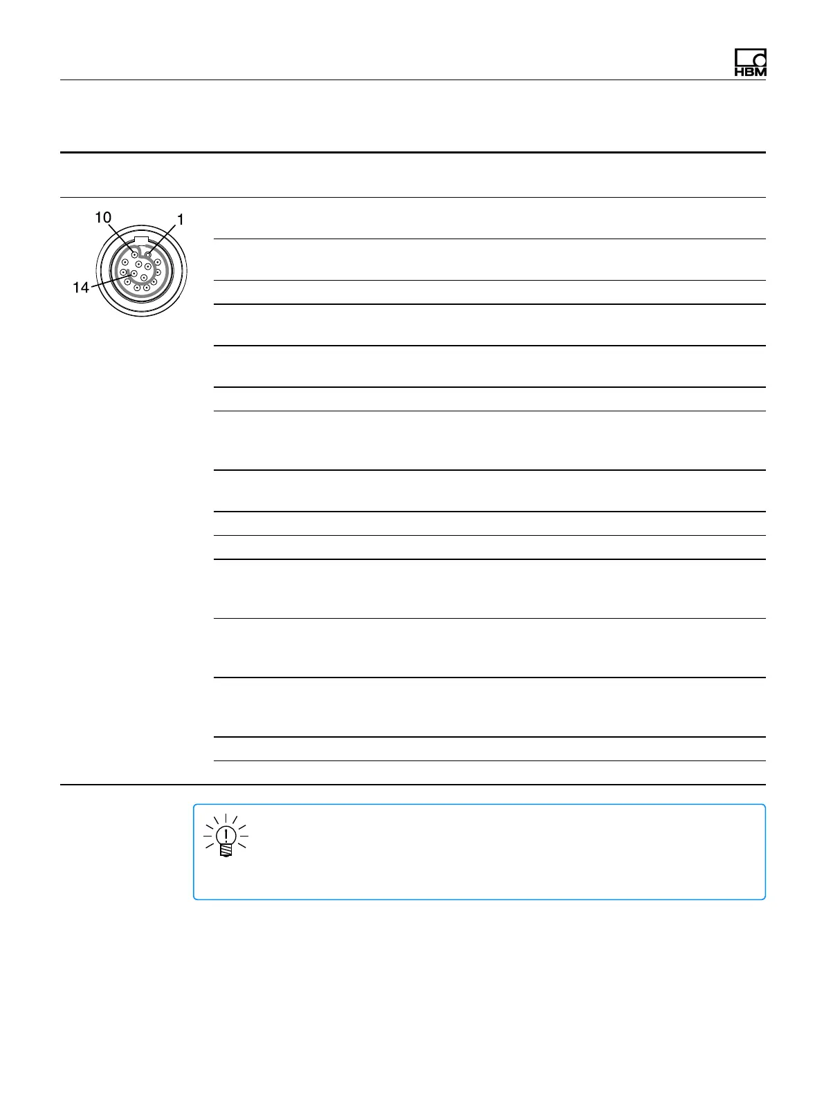
MX840B-R pin assignments
Connect sensors via the 14-pin ODU MINI-SNAP connectors.
Connector Pin Connection
Wire Color
(1-KAB183 or 1-KAB184)
pin side of cable
1 Excitation (-)
Zeroing pulse (-)
Black
2 Excitation (+)
Zeroing pulse (+)
Blue
3 Voltage input 10 V (+), 60 V (+) White/Black
4 Signal ground
jumper to pin 5
Red/Black
5 Ground cable detect
jumper to pin 4
Pink/Black
6 Current input 20 mA (+) Yellow/Black
7 Measurement signal (+)
Voltage input 100 mV (+)
f
1
(-)
White
8 Measurement signal (-)
f
1
(+)
Red
9 Active sensor supply 5...24 V (0 V) Brown
10 Active sensor supply 5...24 V (+) Yellow
11 Sense (-)
f
2
(-)
CAN H
Grey
12 Sense (+)
f
2
(+)
CAN L
Green
13 TEDS (-)
Ground frequency measurement
CAN Ground
Grey/Black
14 TEDS (+) Green/Black
Shield Shield --
NOTE
Connection between pins 4 and 5 is necessary for all transducers. Note that the
sensor connector must have a connection between pins 1 and 11 for compatibility
with the MX1615B-R module.