4 Modules
56 A04089_07_E00_02 HBM: public MX Modules
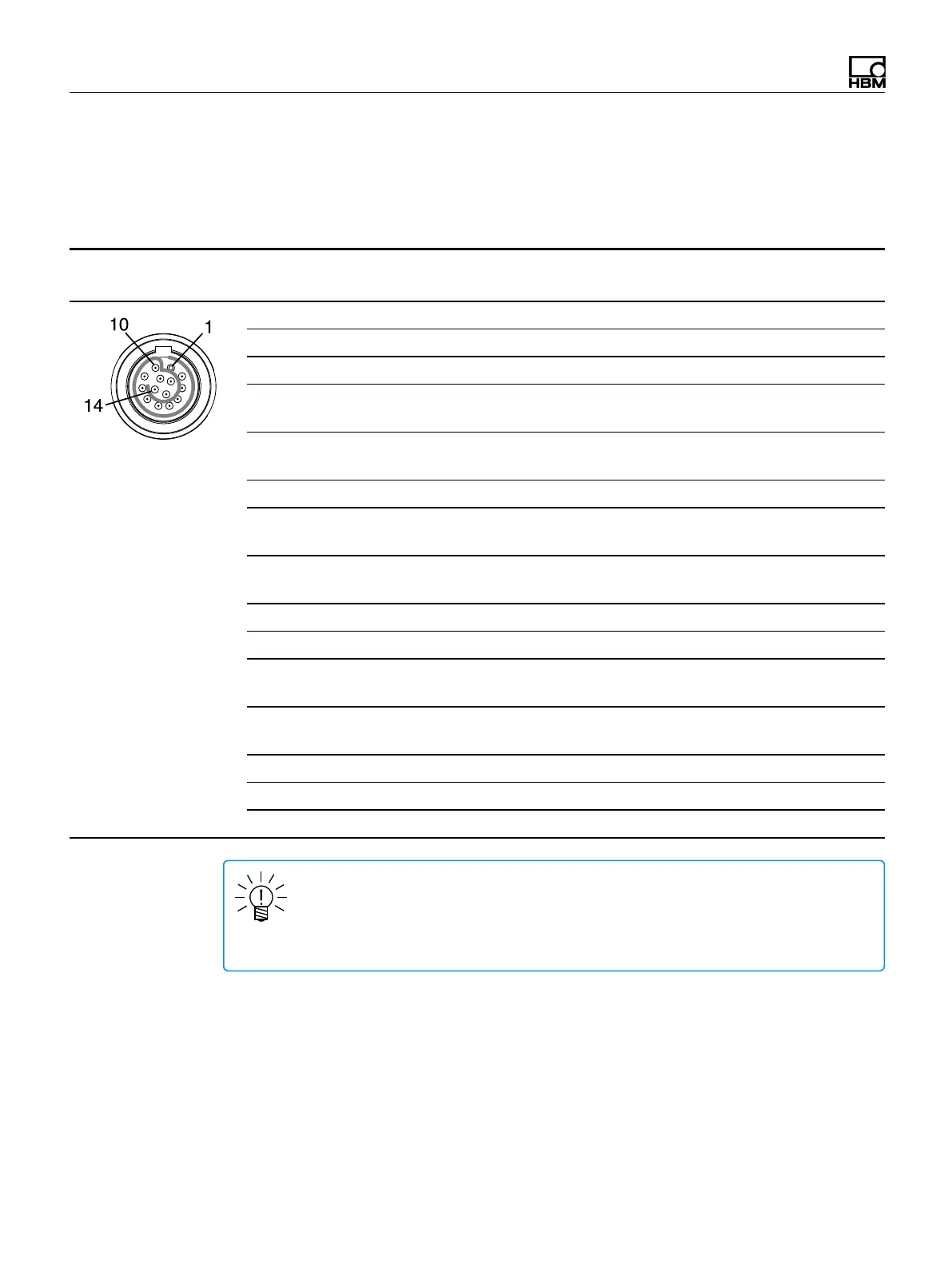
MX460B-R pin assignments
So that insertion or removal of a transducer connection can be unmistakably
identified, Pin 4 and Pin 5 in the connector plug must be bridged! If this bridge is
missing, no measurement values will be recorded at the connection!
Connect sensors via the 14-pin ODU MINI-SNAP connectors.
Connector Pin Connection
Wire Color
(1-KAB183 or 1-KAB184)
pin side of cable
1 Reference pulse 0° (zeroing pulse) (-) Black
2 Reference pulse 0° (zeroing pulse) (+) Blue
3 f
1
AC+ (for passive inductive transducers) White/Black
4 Reference voltage Vref (2.5 V)
jumper to pin 5
Red/Black
5 Plug-in detection
jumper to pin 4
Pink/Black
6 No function Yellow/Black
7 Frequency input
f
1
(-)
White
8 Frequency input
f
1
(+)
Red
9 Active sensor supply 5...24 V (0 V) Brown
10 Active sensor supply 5...24 V (+) Yellow
11 Frequency input
f
2
(-)
Grey
12 Frequency input
f
2
(+)
Green
13 Signal ground, TEDS (-) Grey/Black
14 TEDS (+) Green/Black
Shield Shield --
NOTE
Connection between pins 4 and 5 is necessary for all transducers. Note that the
sensor connector must have a connection between pins 1 and 11 for compatibility
with the MX1615B-R module.