28
1. Naming the process
2. Selecting conguration (one of ve previously imported,
depending on the diameter of the currently installed nozzle).
3. Selecting lament
4. Setting layer height (print quality) . Different layer heights are
available depending on nozzle diameter
5. Model interior ll percentage The higher the interior ll
percentage, the more resistant model, but higher material
consumption and longer print time.
If the interior ll percentage is too low, pillowing
can occur on the upper surfaces of your model!
Using the interior ll percentage lower than 15% is
not recommended.
6. Generating support structures.
This option may only be deselected in special
cases! We recommend that the Generate Support
option should be enabled (selected)
7. Selecting models affected by the process
8. Saving changes to the conguration
9. Adding new conguration
10. Removing conguration
11. Advanced process parameters
6.7 DISPLAYING PRINT PREVIEW AND EXPORTING CONTROL COMMANDS
Once the model is correctly oriented on the build platform and basic process parameters have been congured, you can proceed to
generating control commands.
Use the Prepare to Print button. The program will start generating control commands for your 3D printer. It may take between a few
seconds to several minutes, depending on the complexity of your model, the accuracy of the triangle inll pattern of the STL le and
the computing power of the computer. Once the travel paths are generated the program will proceed to print preview.
Section 1 contains information regarding the estimated print time, length and weight of material necessary to print your model and
the cost of consumed material.
In section 2 you decide which elements of the print preview are shown:
• Build table – a preview of the build platform
• Toolhead – a preview of the print head
• Travel moves – showing idle movements of the print head
• Retractions – showing retraction points
• Coloring – options for colors used to represent different features of your model (movement speed – depending on the print head
linear speed, active toolhead – depending on the currently selected print head, feature type – depending on the type of model
feature that is printed)
Slider (5) allows you to keep track of the building of your model, line-by-line or layer-by-layer.
In section 2 you change default settings for displaying print preview:
1. deselect the Travel moves option
2. from Coloring drop-down list select Feature Type. This allows you a much more clear preview of the printed model.
Button Save Toolpaths to Disc (3) exports the control instructions to a .gcode le, which is then saved on the SD card of your printer.
To return to the parameter edit mode use the Exit Preview Mode pushbutton (4)
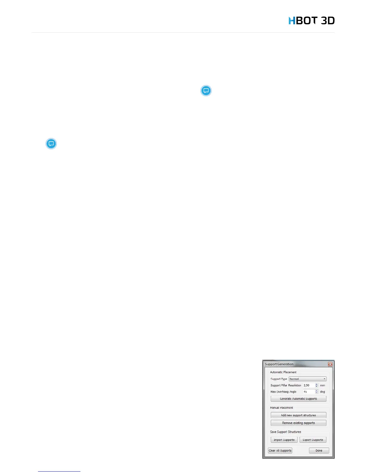
6.8 EDITING SUPPORT STRUCTURES
Depending on the requirements of your model, it is possible to manually edit support structures.
From menu bar select ToolsCustomize Support Structures.
Support Type
In the rst eld select the type of generated support structures. The rst option generates supports
everywhere, where model’s overhang angle is greater than the allowable one (Max Overhang
Angle). The second option From Build Platform Only will only generate supports between the
printing platform and the model.
Resolution
In the Support Pillar Resolution eld you set the resolution of generating the preview of support
structures. This parameter determines how the model exactly will be supported, but without setting
the inll density of support structures.
To generate supports use the Generate Automatic Supports button.