33
6.10 SAVING A PROJECT
Simplify3D Software enables you to save the entire project to a *.factory le. It allows you to save the arrangement of your models on
the printing platform and all settings to an external le.
To save a new project choose FileSave Factory File As…
To save changes to a previously created project choose FileSave Factory File.
6.11 ADDITIONAL SOFTWARE OPTIONS
Preview of a generated gcode le
To open a graphical preview of a previously generated .gcode le, select FilePreview G-Code File… from the menu bar.
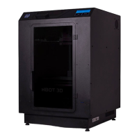
Grouping loaded models
For easier manipulation of the loaded models it is possible to create a group of models. Creating a group of models allows you to
move, scale, rotate and copy multiple models at a time.
To add models to a group, press and hold the SHIFT key and click model names that you want to group. Then, from the menu bar
select EditGroup Selection. Double-clicking lets you edit the name of the new group.
To ungroup multiple models select Edit
Ungroup Selection
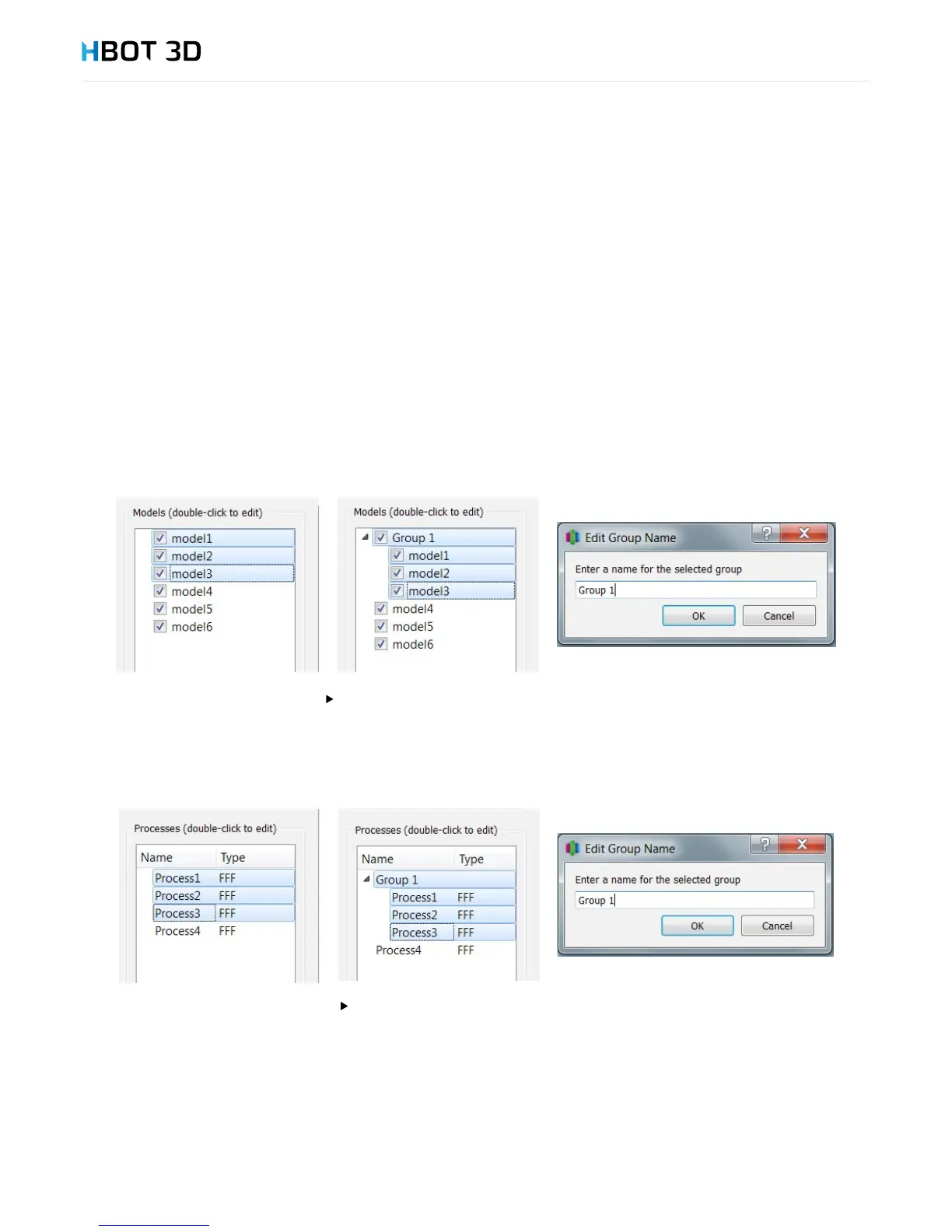
Grouping processes
Similarly to creating groups of models, it is possible to create groups of processes. To add multiple process to a new group, press and
hold the SHIFT key, select the processes and then select EditGroup Selection. To change a name of the created group, double
click its name and enter a new group name in the pop-up window.
To ungroup multiple processes select Edit
Ungroup Selection
Separating an STL le into individual parts
When generating an .STL le based on a model composed of multiple elements in an external CAD software it may happen that
Simplify3D Software generates an incorrect .gcode le when combining these elements. If this is the case, it is necessary to rst separate
the components of the combined .STL le and then allow the software to combine these elements when generating control commands.
To separate components of an .STL le select the MeshSeparate Connected Surfaces option from the menu bar. Depending on
model size and its complexity it can take up to several minutes. Following separation, all components of the .STL le will appear as new
models on the list of loaded models.