Chapter 7. How to Use Speed Servo
7-2
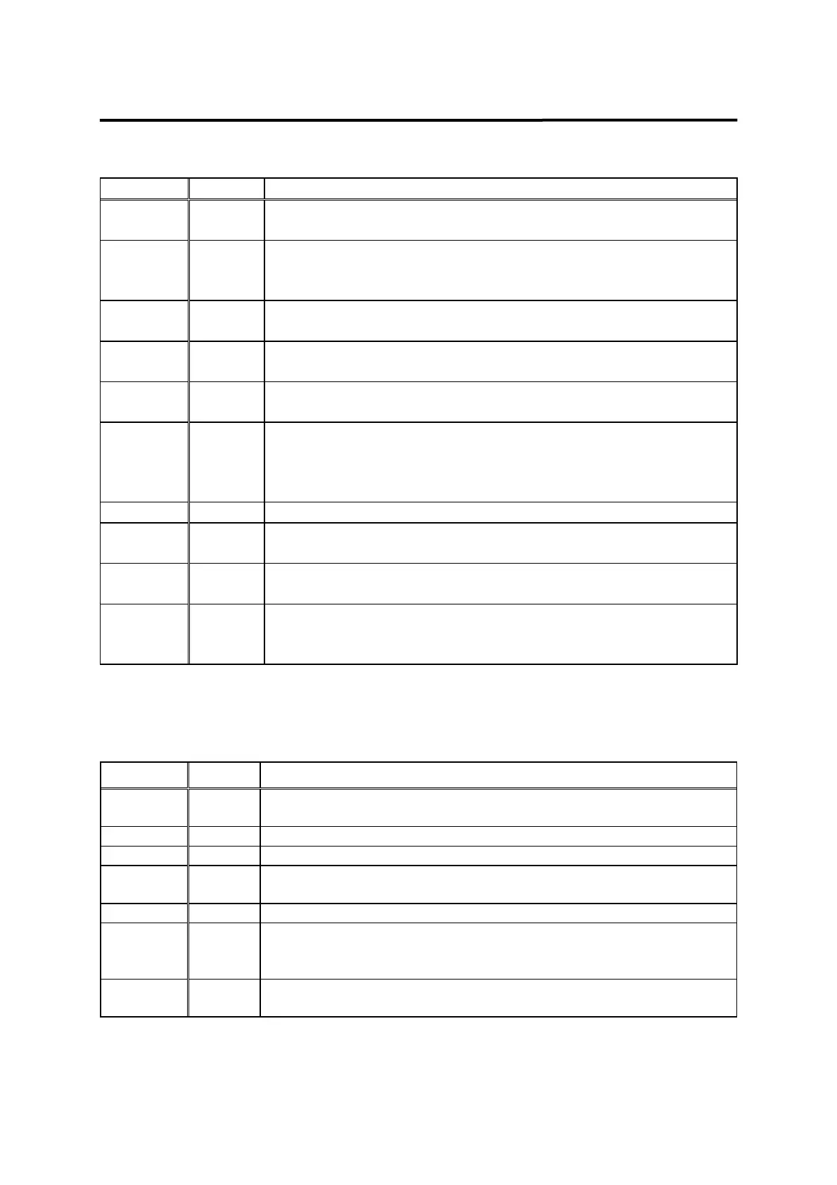
7.2.1 Input contact signal function and use table
Name Pin No. Function and Use
SVONEN 18
ON: Servo start command
OFF: Servo start command reset
DIR 16
Selects servo rotation direction
(Off: Command direction rotation, ON: Counter-command direction
rotation)
STOP/
START
13
Forcibly zeros (stops) the speed command value, or starts
operation. (Can be selected from parameter P2-29)
CCWLIM 15
OFF: Motor CCW running limited
ON: Motor CCW running allowed
CWLIM 40
OFF: Motor CW running limited
ON: Motor CW running allowed
ESTOP 39
Forcibly ignores all input status of the servo drivers in case of
external emergency, and shuts off (free-run) motor operation after
rapidly decelerating the motor.
(Contact type can be selected from parameter P2-30)
ALMRST 38 Resets alarm status if turned ON
PI/P 41
Selects speed control mode (Turned OFF during normal operation)
ON: Proportional control, OFF: Proportional integration control
TLIM 14
ON: Analog torque limit; Off: Digital torque limit.
See section 7.6.
SPD1
SPD2
SPD3
43
17
42
Selects rotation speed command by the combination of SPD 1, 2
and 3.
See section 7.7.
Where ON: Applicable contact is connected to "GND24".
OFF: Applicable contact is connected to "+24V", or applicable contact not connected.
7.2.2 Output contact signal function and use table
Name Pin No. Function and Use
RDY 21
ON: Main power and auxiliary power are connected to servo
without any alarm.
INSPD 22 ON: Motor speed reached designated level.
ZSPD 47 ON: Motor speed is zero.
BRAKE 48
Output signal for external machine brake drive
ON: Brake reset, OFF: Brake drive
ALARM 20 ON: Normal status, OFF: Alarm detected
A_CODE0
A_CODE1
A_CODE2
45
19
44
Displays alarm type.
See the table below [Alarm Code output status].
TRQOUT 46
ON: Servo is under torque limit.
See section 7.6 for information on output torque limit.
Where ON: Applicable contact is connected to "GND24".
OFF: Applicable contact is connected to "+24V", or applicable contact not connected.