Chapter 3. Wiring and Signals
3-17
3.5 Description of CN2 Wiring and Signals
3.5.1 Wiring and signals of incremental encoder
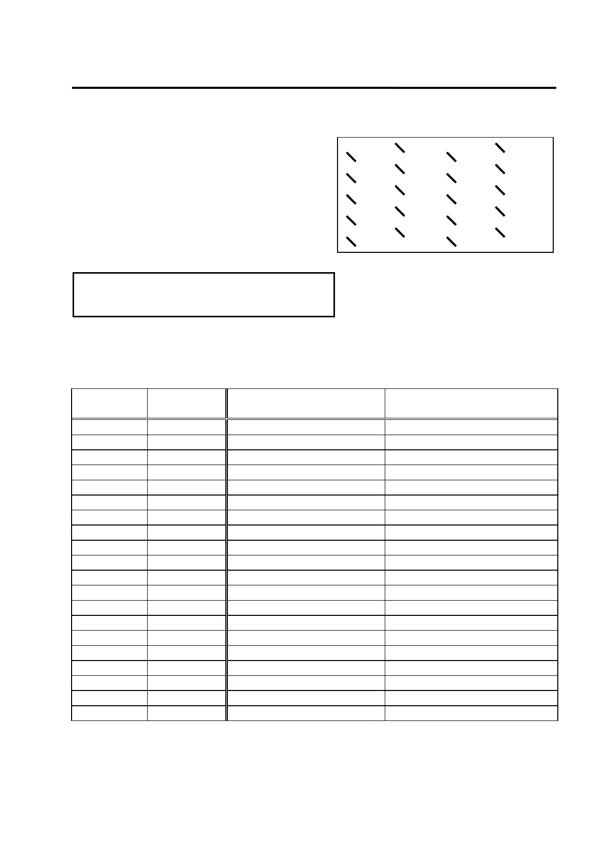
CN2 is a connecter located in the right center of the
front part of the drive system. This is used to
connect the drive system and servo motor encoder.
The right figure shows pin array viewed from the
user connector. Encoder signal varies slightly
according to the types of encoder.
[Based on the soldered side
of the user connector]
(Danger!!) Product may be damaged by burn
in case the servo is started without
connectin
the CN2 encoder wirin
.
Wiring of CN2 and the FMA-CN series AC servo motor's incremental encoder is shown on the
following table.
(Caution!) When absolute value encoder is used, refer to Chapter 3.5.2. Interface and Use of
Absolute Value Encoder.
CN2 pin No. Signal name
Motor (
□60, 80 series) side
encoder connector pin No.
Motor (□130, 180 series) side
encoder connector pin No.
1 PW 11 P
2 /PW 12 R
3 PV 9 M
4 /PV 10 N
5 PU 7 K
6 /PU 8 L
7
8
9 GND 14 G
10
11 /PZ 6 F
12 F.G. 15 J
13 /PB 4 D
14 PZ 5 E
15 /PA 2 B
16 PB 3 C
17
18 PA 1 A
19 Vcc( DC 5V ) 13 H
20
(Caution!) Connect the earth cable of the encoder wiring to F.G.
(Caution!) Cable specifications: AWG24 x 9 pair twist, shield cable (maximum length: 20 m)
COVV(Maker : LS cable) or equivalent.
13:/PB
9:GND
11:/PZ
8:
12:FG
10:
14:PZ
16:PB
18:PA
17:
15:/PA
19:Vcc
20:
PIN array of CN2
1:PW
3:PV
5:PU
4:/PV
2:/PW
6:/PU
7: